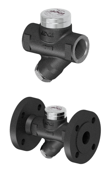
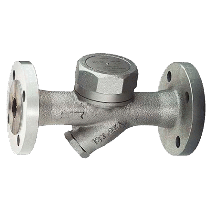
THERMOSTATIC CONDENSATE TRAP WITH AIR BREATHER THREADED / FLANGED ADCA TH32Y – TH32Y / CK
TECHNICAL DESCRIPTION
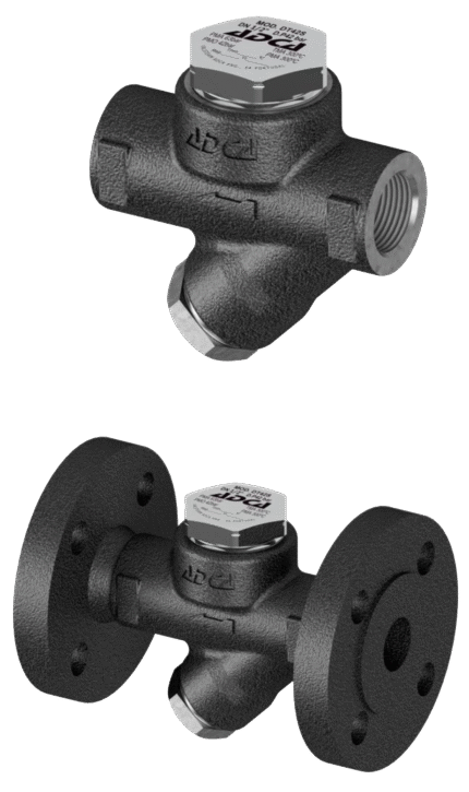
Thermostatic steam traps TH32Y series for steam with automatic air venting. They are specially designed for installation in industrial equipment such as sterilizers, food processing equipment, laundry equipment and in chemical industry facilities.
Connection is threaded or flanged.
MAIN FUNCTIONS
Controlled discharge.
Drains condensate at a temperature close to that of the steam.
Thermostat for different subcoolings (5ºK to 30ºK).
Excellent deaeration.
Works with moderately superheated steam.
Built-in filter.
WORKING FLUID / MEDIUM
Superheated steam
EXECUTION
• LC – low capacity • Integral check valve • Purge valve.
MODELS
• TH32Y • TH32Y-CK (with check valve)
INSTALLATION RECOMMENDATIONS
• Horizontal installation is recommended. • Can be installed in any position, according to the manufacturer’s installation and maintenance instructions.
JOIN
• flanged • threaded • welded (on request)
Dimensions:1/2″ – 1″ / DN 15 – 25
Materials
| No. | DETAILS | MATERIALS |
|---|---|---|
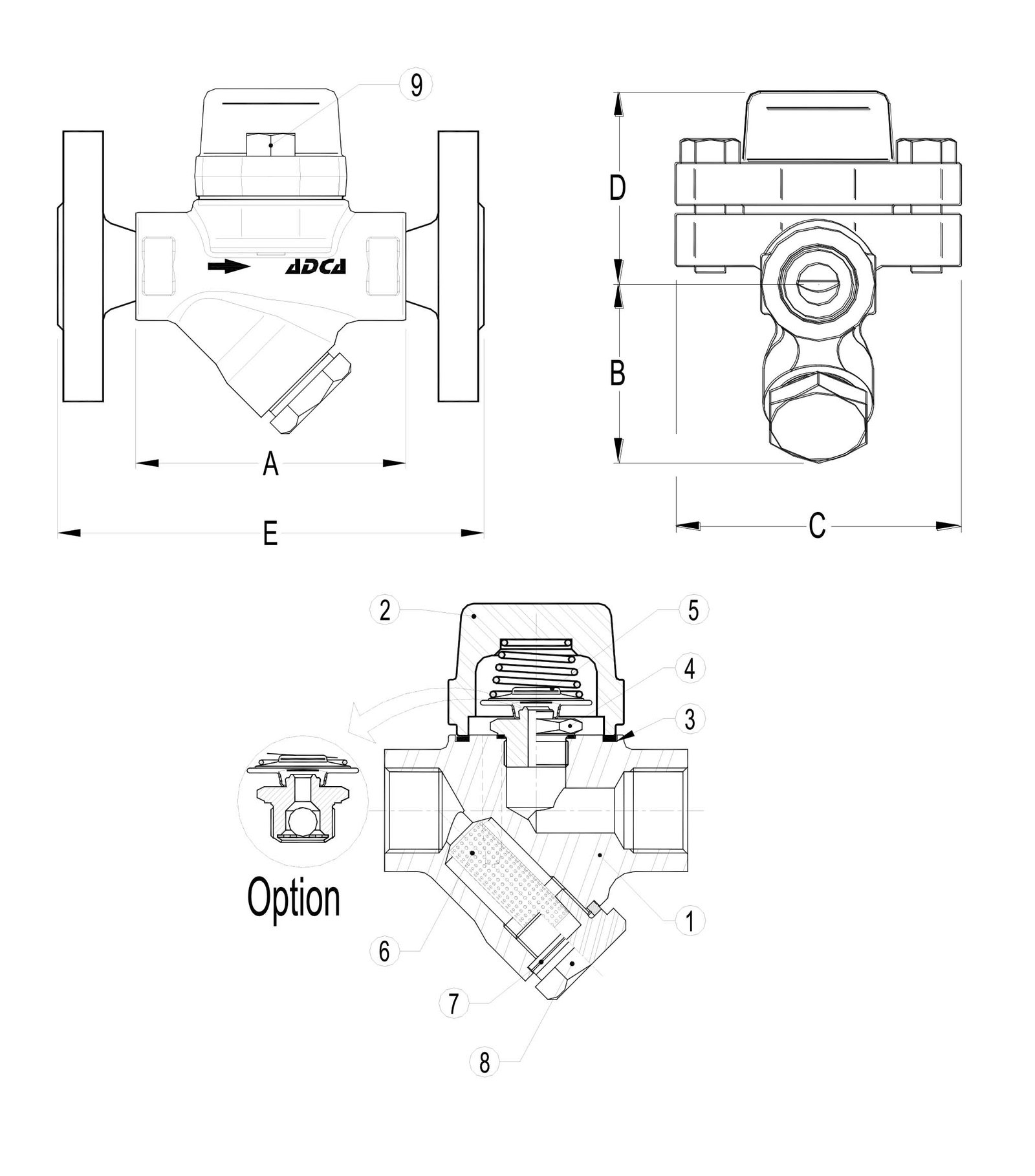
| 1 | Body | P250GH / 1.0460 |
| 2 | Lid | P250GH / 1.0460 |
| 3 | Garnish | stainless steel/graphite |
| 4 | Valve | AISI 304 / 1.4301 |
| 5 | Thermostatic element | stainless steel |
| 6 | Filter | AISI 304 / 1.4301 |
| 7 | Garnish | stainless steel/graphite |
| 8 | Filter cover | A105 / 1.0432 |
| 9 | Bolts | A2-70 |
Features
| SPECIFICATION | |
|---|---|
| Standard | DIN |
| Threaded connection | ISO 7 / 1 Rp (BS21) |
| Flange connection | EN 1092-1 PN40 or ANSI |
| Lid connection | bolted |
| Execution | straight |
| Management | automatically |
| Venting | automatically |
| Installation | horizontal |
Flow rate
| PASSABILITY kg/h | ||||||||||||||||
|---|---|---|---|---|---|---|---|---|---|---|---|---|---|---|---|---|
| MODEL | DN | DIFFERENTIAL PRESSURE (bar) | ||||||||||||||
| 0.2 | 0.3 | 0.5 | 1 | 1.5 | 2 | 3 | 4 | 6 | 8 | 10 | 13 | 15 | 20 | 22 | ||
| TH32Y | 15 - 25 | 70 | 120 | 140 | 255 | 330 | 385 | 455 | 510 | 600 | 670 | 700 | 720 | 750 | 775 | 790 |
| TH32YLC | 15 - 25 | 45 | 55 | 70 | 95 | 125 | 135 | 180 | 200 | 270 | 315 | 330 | 360 | 370 | 405 | 415 |
Limits
| MAXIMUM OPERATING PARAMETERS | ||
|---|---|---|
| Maximum working pressure / Bars | T max. [°C] | |
| FLANGE PN 40 / ANSI #300 | FLANGE ANSI #150 | |
| 40 bar | 19.3 bar | 50 °C |
| 35 bar | 15.8 bar | 150 °C |
| 30.4 bar | 12.2 bar | 250 °C |
| 27.6 bar | 10.2 bar | 300 °C |
| DIMENSIONS (mm) | |||||||||||
|---|---|---|---|---|---|---|---|---|---|---|---|
| Threaded or welded | Flange EN PN 16 / PN 40 |
Flanged ANSI 150 |
Flanged ANSI 300 |
||||||||
| DN | A | B | C | D | kg | E | kg | E | kg | E | kg |
| 15 - 1/2" | 95 | 59 | 95 | 65 | 1.6 | 150 | 3.2 | 150 | 2.7 | 150 | 3.5 |
| 20 - 3/4" | 95 | 59 | 95 | 65 | 1.6 | 150 | 3.9 | 150 | 3.1 | 150 | 4.7 |
| 25 - 1" | 95 | 65 | 95 | 65 | 1.8 | 160 | 4.7 | 160 | 4.3 | 160 | 5.9 |
Related products
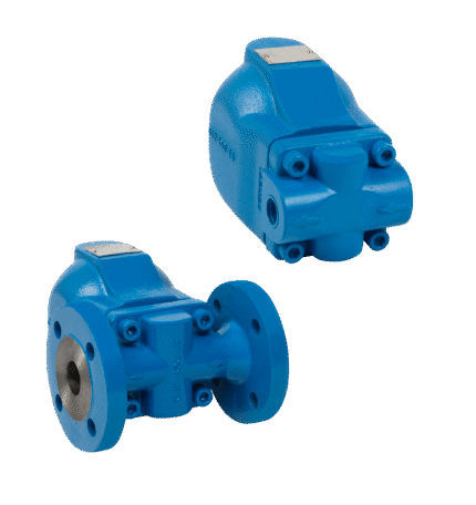
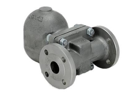
CONDENSATE SEPARATOR FLOAT THREADED / FLANGE ADCA FLT 32
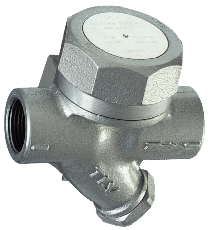
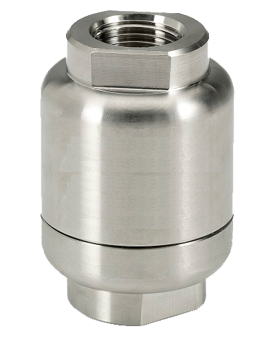
CONDENSATE SEPARATOR THERMODYNAMIC FLANGE TLV AF3N
CONDENSATE TRAP WITH AIR BREATHER ADCA TSS 22 THREADED
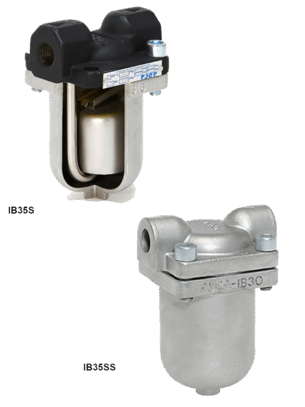
CONDENSATE TRAPPER WITH INVERTED PISTON ADCA IB35S / IB35SS
FLOAT FLANGE / THREADED CONDENSATE SEPARATOR ADCA FLT 14I – DN 40-50
FLOAT FLANGE / THREADED CONDENSATOR SEPARATOR ADCA FLT 14I – DN 25HC
THERMODYNAMIC THREADED / FLANGED CONDENSATE TRAP ADCA DT 42/2