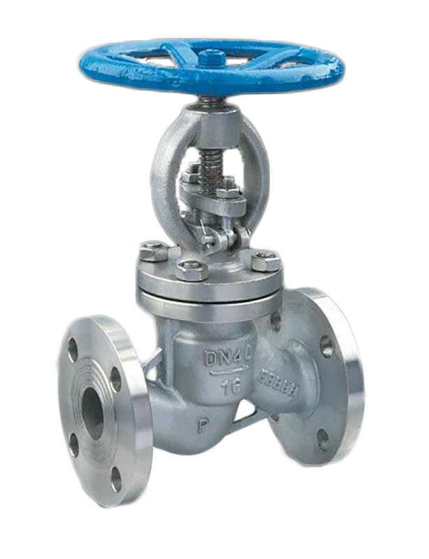
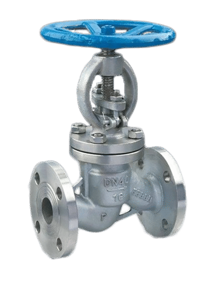
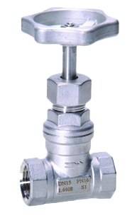
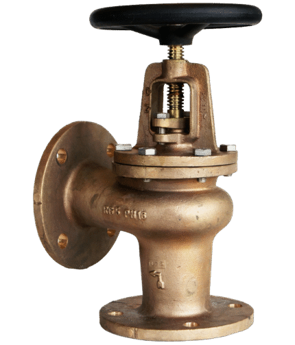
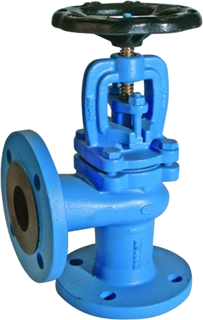
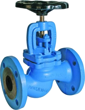
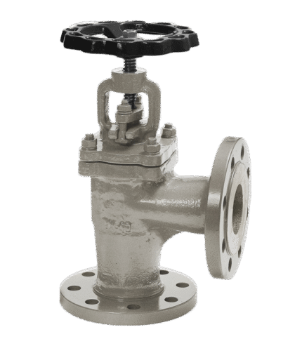
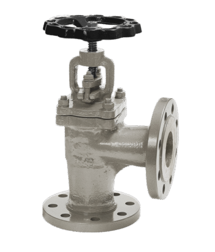
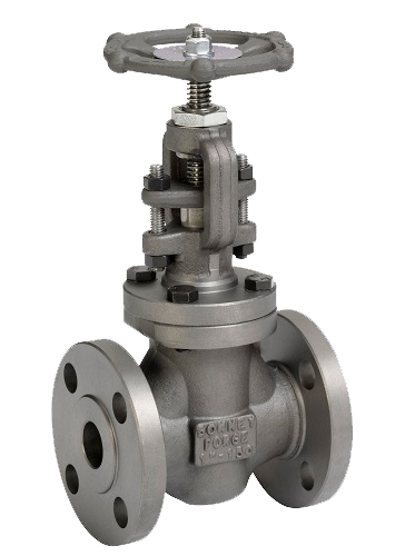
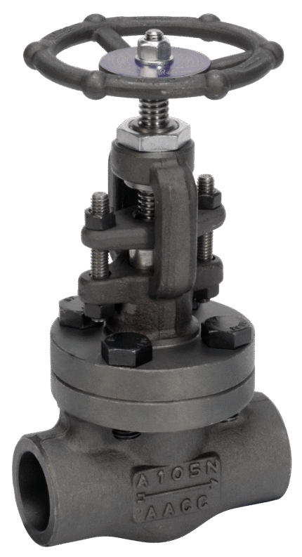
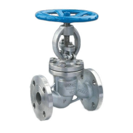
STAINLESS STEEL VALVE STRAIGHT DIN 3202 F1, PN 40
TECHNICAL DESCRIPTION
Straight valve, with flange connection. Possible variations of functions depending on the design.
• shut-off valve
• regulating valve
• check valve.
Sealing of the plug (valve) – metal to metal.
Type of the spindle (spindle) – extracting.
WORKING FLUID / MEDIUM
Water, steam, corrosive fluids, steam, thermal oil, fuels, lubricating oils and flammable hydraulic oils, petroleum, non-flammable hydraulic fluids, boiler feed water, condensate, seawater.
OPTIONS
Closing spring when used as a check valve.
Dimensions:DN 15 – 200
Този продукт вече е в списъка ви със заявки за оферта. (This product is already in your quote request list.)
Additional information
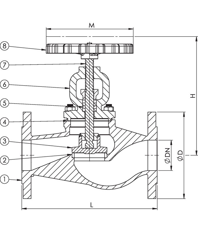
Materials
| No. | DETAILS | MATERIALS |
|---|---|---|
| 1 | Body | stainless steel 1.4408 (AISI AISI 316) |
| 2 | Saddle | stainless steel 1.4401 (AISI AISI 316) |
| 3 | Valve | stainless steel 1.4401 (AISI AISI 316) |
| 4 | Garnish | graphite |
| 5 | Oil seal | graphite packing |
| 6 | Lid | stainless steel 1.4408 (AISI AISI 316) |
| 7 | Spindle | stainless steel 1.4401 (AISI AISI 316) |
| 8 | Handwheel | ductile iron EN-JS1040 (GGG 40) |
Features
| SPECIFICATION | |
|---|---|
| Standard | DIN 3202 F1 |
| Joining | EN 1092-2 |
| Construction length | EN 558, series 1 |
| Lid connection | bolted |
| Execution | straight |
| Joining | flanged |
| Management | manually with wheel |
| Drive | multi-turn |
| T max. °C | 350 °C |
Dimensions
| DN | PN | Flanges/PN | L | D | ØP* | nxd | H | M | Weight (kg) |
|---|---|---|---|---|---|---|---|---|---|
| 15 | 40 | 40 | 130 | 95 | 65 | 4x14 | 165 | 120 | 3.9 |
| 20 | 40 | 40 | 150 | 105 | 75 | 4x14 | 165 | 120 | 4.3 |
| 25 | 40 | 40 | 160 | 115 | 85 | 4x14 | 180 | 140 | 5.4 |
| 32 | 40 | 40 | 180 | 140 | 100 | 4x18 | 180 | 140 | 7 |
| 40 | 40 | 40 | 200 | 150 | 110 | 4x18 | 215 | 160 | 9.5 |
| 50 | 40 | 40 | 230 | 165 | 125 | 4x18 | 230 | 160 | 12.9 |
| 65 | 40 | 40 | 290 | 185 | 145 | 8x18 | 245 | 180 | 17.4 |
| 80 | 40 | 40 | 310 | 200 | 160 | 8x18 | 295 | 210 | 24.5 |
| 100 | 40 | 40 | 350 | 220 | 190 | 8x22 | 325 | 225 | 34.7 |
| 125 | 40 | 40 | 400 | 250 | 220 | 8x26 | 360 | 250 | 52 |
| 150 | 40 | 40 | 480 | 285 | 250 | 8x26 | 425 | 300 | 78 |
| 200 | 40 | 40 | 600 | 340 | 320 | 12x30 | 505 | 400 | 247 |
| Note: The dimensions in column ØP should be considered as the diameters of the bolt circle, as the latter are not indicated in the drawing. | |||||||||

