
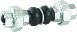
RUBBER FLANGED COMPENSATORS
TECHNICAL DESCRIPTION
• They are used in various joints with the presence of vibrations, axial and lateral displacements
• They are also used as joints in pipelines operating with pressure and vacuum
Dimensions:DN 32 – 600
Additional information

Materials
| No. | DETAILS | MATERIALS |
|---|---|---|
| 1 | Inner and outer part | EPDM/NBR rubber |
| 2 | Reinforcement | nylon reinforcement |
| 3 | Flanges | galvanized steel |
| 4 | Bracket | hardened steel |
Features
| SPECIFICATION | |
|---|---|
| Standard | DIN |
| Rubber compensator | EPDM |
| DN 32 - 300 | PN 16 |
| DN 350 - 600 | PN 10 |
Dimensions
| DN | L | ØD | ØD1 | MAXIMUM RECORDED DISPLACEMENTS (mm) | weight | |||
|---|---|---|---|---|---|---|---|---|
| (mm) | (mm) | (mm) | contraction | stretching | lateral | angular | kg | |
| 32 | 95 | 29 | 69 | 8 | 4 | 8 | 15° | 2.79 |
| 40 | 95 | 37 | 79 | 8 | 4 | 8 | 15° | 3.59 |
| 50 | 105 | 47 | 90 | 8 | 4 | 8 | 15° | 4.23 |
| 65 | 115 | 57 | 108 | 12 | 6 | 10 | 15° | 4.74 |
| 80 | 130 | 74 | 124 | 12 | 10 | 12 | 15° | 6.27 |
| 100 | 135 | 91 | 145 | 18 | 10 | 12 | 15° | 6.47 |
| 125 | 170 | 119 | 179 | 18 | 10 | 12 | 15° | 9.4 |
| 150 | 180 | 145 | 209 | 18 | 10 | 12 | 15° | 12.75 |
| 200 | 205 | 199 | 261 | 20 | 14 | 18 | 15° | 17.73 |
| 250 | 240 | 241 | 320 | 22 | 14 | 18 | 15° | 23.27 |
| 300 | 260 | 294 | 370 | 24 | 14 | 18 | 15° | 29.4 |
| 350 | 265 | 331 | 420 | 25 | 16 | 18 | 15° | 41.3 |
| 400 | 265 | 372 | 473 | 25 | 16 | 18 | 15° | 46.85 |
| 450 | 200 | 431 | 532 | 20 | 12 | 18 | 15° | 55.18 |
| 500 | 200 | 486 | 587 | 20 | 12 | 18 | 15° | 65 |
| 600 | 250 | 591 | 685 | 20 | 12 | 18 | 15° | 74.5 |
Related products
Select options
This product has multiple variants. The options may be chosen on the product page
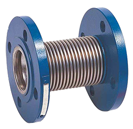
STAINLESS STEEL LENS EXPANSION JOINTS ON FLANGES
Select options
This product has multiple variants. The options may be chosen on the product page
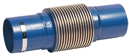
STAINLESS STEEL LENS EXPANSION JOINTS WITH WELDED END
Select options
This product has multiple variants. The options may be chosen on the product page