
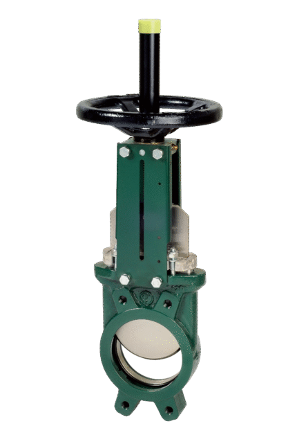
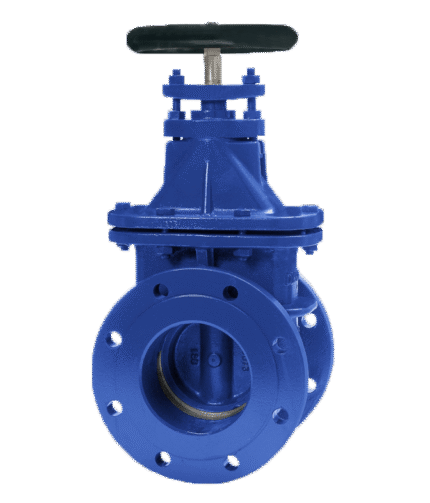
KNIFE GATE VALVE CAST IRON VG3400-001 NON RISING SPINDLE DIN PN 10-16
TECHNICAL DESCRIPTION
Range: from DN 50 to DN 600.
ON / OFF function or regulation.
Threaded mounting between PN10 flanges.
One-way tightening, clockwise.
The wedge is guided in the body with a small clearance.
Packing: Packing and O-ring to provide elasticity and reduce operating torque.
Regulation: Ability to regulate high density fluids.
Seal: Diaphragm ring.
WORKING FLUID / MEDIUM
They are used in installations for the transfer of thick technological slurries, water, water processing, sewage, the chemical industry, wine production and for the transfer of dry mixtures.
OPTIONS
Different body and disc materials on request:
EXECUTION
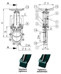
• Seal: metal / metal
• Seal: metal / rubber (soft sealing)
Dimensions: DN 50 – 600
Additional information
Materials
| No. | DETAILS | MATERIALS |
|---|---|---|
| 14 | O-ring | stainless steel 316 |
| 13 | Flywheel | grey cast iron DIN GG 25 |
| 12 | Nut | stainless steel |
| 11 | Thrust washer | bronze RG50 |
| 10 | Sealant | NBR rubber |
| 9 | Sealant | NBR rubber |
| 8.1 | Stuffing box | aluminum DN50-450 |
| 8.2 | Stuffing box | steel DN500-600 |
| 7 | Friction washer | bronze RG5 |
| 6 | Nut | galvanized steel |
| 5 | Plank | steel + epoxy coating |
| 4 | Spindle | stainless steel |
| 3 | Wedge | stainless steel ASTM AISI 304 BS |
| 2 | Stuffing box sealant | Teflon PTFE |
| 1 | Body | cast iron EN-GJL-250 |
Features
| SPECIFICATION | |
|---|---|
| Construction standard: | EN 2014/68/EU |
| Atex: | ATEX II 2 GD c and ATEX II 3 GD c. |
| Execution: | straight |
| Connection: | between flanges of EN 1092-2 PN10 on thread |
| Management: | flywheel |
| Drive: | multi-turn |
| Tests: | EN 12266-1, DIN 3230 |
| Operating temperature. °C | - 10°C to + 80°C |
| Maximum operating pressures: | |
| DN 50-250 | 10 bar |
| DN 300-450 | 7 bar |
| DN 500-600 | 4 bar |
Dimensions
| DN | A | B | C | D | Ø V | H | Ø K | n | Ø M | Weight (kg) | |
|---|---|---|---|---|---|---|---|---|---|---|---|
| mm | inches | ||||||||||
| 50 | 2" | 40 | 105 | 124 | 94 | 200 | 291 | 125 | 4 | 4-M16 | 7.5 |
| 65 | 2"1/2 | 40 | 115 | 139 | 94 | 200 | 318 | 145 | 4 | 4-MI 6 | 8.8 |
| 80 | 3" | 50 | 124 | 154 | 94 | 200 | 342 | 160 | 8 | 4-M16 | 9.4 |
| 100 | 4" | 50 | 140 | 174 | 94 | 200 | 383 | 180 | 8 | 4-M16 | 11.5 |
| 125 | 5" | 50 | 150 | 189 | 100 | 250 | 420 | 210 | 8 | 4-M16 | 15.4 |
| 150 | 6" | 60 | 175 | 220 | 101 | 250 | 471 | 240 | 8 | 4-M20 | 18.5 |
| 200 | 8" | 60 | 205 | 275 | 124 | 310 | 577 | 295 | 8 | 4-M20 | 34.8 |
| 250 | 10" | 70 | 250 | 326 | 126 | 310 | 677 | 350 | 12 | 8-M20 | 47.0 |
| 300 | 12" | 70 | 300 | 380 | 128 | 310 | 777 | 400 | 12 | 8-M20 | 61.0 |
| 350 | 14" | 96 | 339 | 438 | 290 | 500 | 939 | 460 | 16 | 10-M20 | 117.0 |
| 400 | 16" | 100 | 392 | 494 | 290 | 500 | 1037 | 515 | 16 | 10-M24 | 151.0 |
| 450 | 18" | 106 | 434 | 547 | 290 | 500 | 1125 | 565 | 20 | 14-M24 | 187.0 |
| 500 | 20" | 110 | 487 | 613 | 290 | 500 | 1237 | 620 | 20 | 14-M24 | 205.0 |
| 600 | 24" | 110 | 592 | 716 | 290 | 500 | 1432 | 725 | 20 | 14-M27 | 292.0 |
Related products
Select options
This product has multiple variants. The options may be chosen on the product page
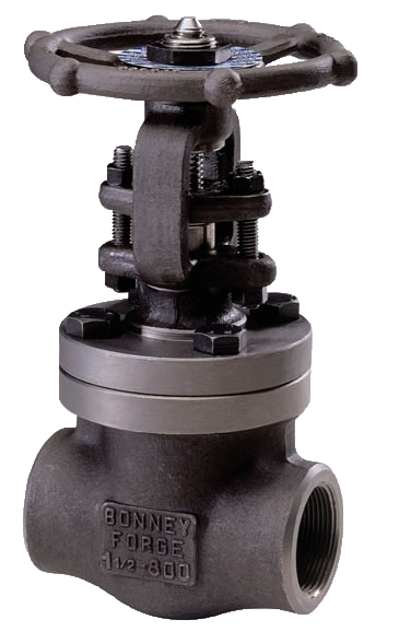
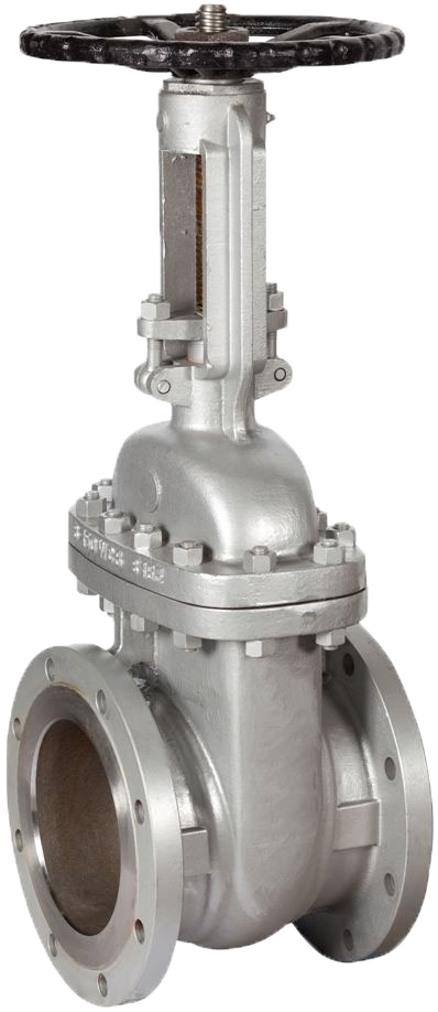
FORGED GATE VALVE STEEL WITH RISING STEM BSP / 800 LBS
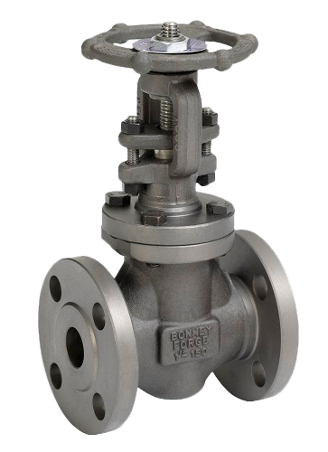
Select options
This product has multiple variants. The options may be chosen on the product page
FORGED GATE VALVE STEEL WITH RISING STEM SW / 150 LBS
Select options
This product has multiple variants. The options may be chosen on the product page
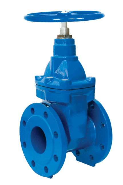
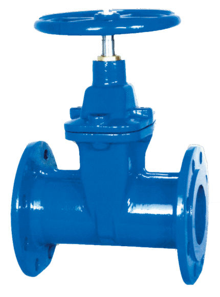
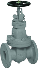
GATE VALVE CAST IRON FOR DRINKING WATER WITH RUBBER COATED WEDGE F5 DIN EN 1171 (DIN 3352 T2)
Select options
This product has multiple variants. The options may be chosen on the product page
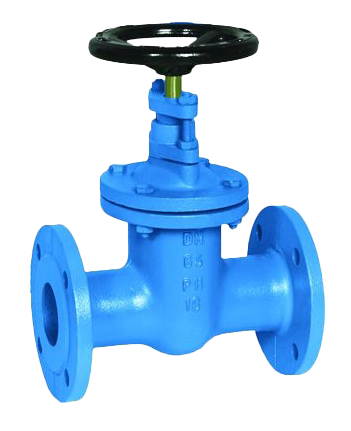
GATE VALVE CAST IRON NON RISING STEM F5 DIN EN 1171 (DIN 3352 T2)
Select options
This product has multiple variants. The options may be chosen on the product page
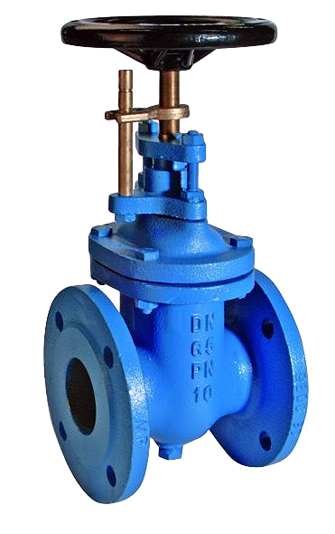
GATE VALVE CAST IRON WITH NON RISING STEM AND POSITION INDICATOR F4 DIN EN 1171 (DIN 3352 T2)
Select options
This product has multiple variants. The options may be chosen on the product page
GATE VALVE JIS 10K JIS F7400 CAST IRON WITH NON RISING STEM AND POSITION INDICATOR
Select options
This product has multiple variants. The options may be chosen on the product page
GATE VALVE STEEL WITH NON RISING STEM F4 DIN
Select options
This product has multiple variants. The options may be chosen on the product page