
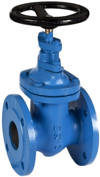
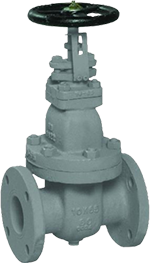
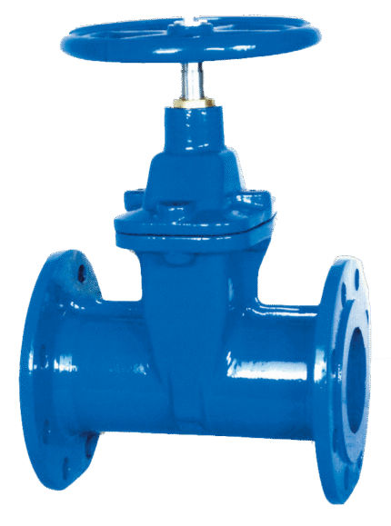
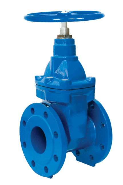
GATE VALVE CAST IRON NON RISING STEM F5 DIN EN 1171 (DIN 3352 T2)
TECHNICAL DESCRIPTION
Cast iron gate valves are shut-off valves and are widely used in industry, industry and shipbuilding. They are mainly used in systems transporting water or other liquid fluids, including fuels, toxic products, seawater and hydraulic oils.
WORKING FLUID / MEDIUM
Water, fuels, lubricating and hydraulic oils, seawater, etc.
OPTIONS
· Different materials for interior trim and seals.
Dimensions: DN 40 – 700
Additional information
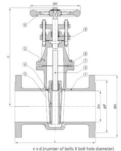
Materials
| No. | DETAILS | MATERIALS |
|---|---|---|
| 1 | Body | cast iron EN-JL1040 (GG25) |
| 2 | Cover | cast iron EN-JL1040 (GG25) |
| 3 | Wedge | cast iron EN-JL1040 (GG25) |
| 4 | Seat | brass CuZn39Pb3 (CW614N) |
| 5 | Stem | brass CuZn39Pb3 (CW614N) |
| 6 | Fasteners | stainless steel AISI 304 |
| 7 | Cover gasket | NBR rubber |
| 8 | Packing seal | packing teflon / PTFE |
| 9 | Flywheel | cast iron EN-JL1040 (GG25) |
Features
| SPECIFICATION | |
|---|---|
| Standard: | F5 DIN EN 1171 (DIN 3352 T2) |
| Joining: | EN 1092-2 |
| Construction length: | EN 558, series 15 |
| Attaching the lid: | bolted |
| Execution: | straight |
| Connection: | flanged |
| Operation: | manual |
| Actuation: | multi-turn |
Dimensions
| DN | PN | Flanges/PN | ØD | ØP* | nxd | L | H | ØR | kg | ||||||
|---|---|---|---|---|---|---|---|---|---|---|---|---|---|---|---|
| PN6 | PN10 | PN16 | PN6 | PN10 | PN16 | PN6 | PN10 | PN16 | |||||||
| 40 | 10 | 6/10/16 | 130 | 150 | 150 | 100 | 110 | 110 | 4x14 | 4x18 | 4x18 | 240 | 240 | 200 | 13 |
| 50 | 10 | 6/10/16 | 140 | 165 | 165 | 110 | 125 | 125 | 4x14 | 4x18 | 4x18 | 250 | 250 | 200 | 14 |
| 65 | 10 | 6/10/16 | 160 | 185 | 185 | 130 | 145 | 145 | 4x14 | 4x18 | 4x18 | 270 | 275 | 250 | 19 |
| 80 | 10 | 6/10/16 | 190 | 200 | 200 | 150 | 160 | 160 | 4x18 | 8x18 | 8x18 | 280 | 285 | 250 | 25 |
| 100 | 10 | 6/10/16 | 210 | 220 | 220 | 170 | 180 | 180 | 4x18 | 8x18 | 8x18 | 300 | 315 | 315 | 30 |
| 125 | 10 | 6/10/16 | 240 | 250 | 250 | 200 | 210 | 210 | 8x18 | 8x18 | 8x18 | 325 | 415 | 315 | 48 |
| 150 | 10 | 6/10/16 | 265 | 285 | 285 | 225 | 240 | 240 | 8x18 | 8x22 | 8x22 | 350 | 435 | 315 | 60 |
| 200 | 6 | 6/10/16 | 320 | 340 | 340 | 280 | 295 | 295 | 8x18 | 8x22 | 12x22 | 400 | 580 | 400 | 97 |
| 250 | 6 | 6/10/16 | 375 | 395 | 405 | 335 | 350 | 355 | 12x18 | 12x22 | 12x26 | 450 | 715 | 500 | 165 |
| 300 | 6 | 6/10/16 | 440 | 445 | 460 | 395 | 400 | 410 | 12x22 | 12x22 | 12x26 | 500 | 770 | 500 | 235 |
| 350 | 4 | 10 | 505 | 460 | 16x22 | 550 | 870 | 500 | 330 | ||||||
| 400 | 4 | 10 | 565 | 515 | 16x26 | 600 | 950 | 600 | 440 | ||||||
| 500 | 4 | 10 | 670 | 620 | 20x26 | 700 | 1210 | 800 | 787 | ||||||
| 600 | 2.5 | 10 | 780 | 725 | 20x30 | 800 | 1340 | 800 | 1060 | ||||||
| 700 | 2.5 | 10 | 895 | 840 | 24x30 | 900 | 1560 | 800 | 1330 | ||||||
| Note: The dimensions in column ØP should be considered as the diameters of the bolt circle, as the latter are not indicated in the drawing. | |||||||||||||||
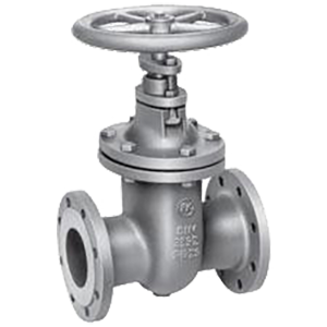
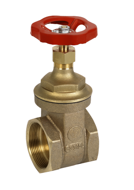
Related products
Select options
This product has multiple variants. The options may be chosen on the product page
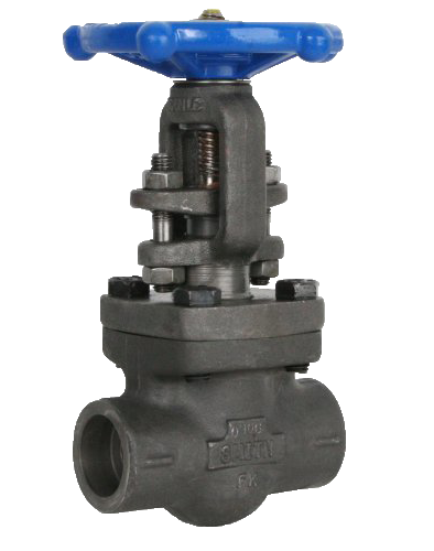
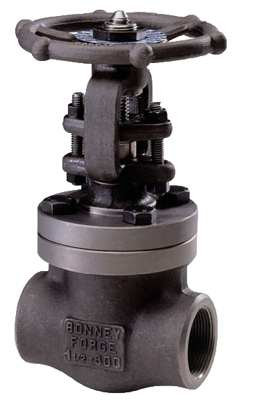
FORGED GATE VALVE CARBON STEEL WITH RISING STEM SW / 800 LBS
Select options
This product has multiple variants. The options may be chosen on the product page
FORGED GATE VALVE STEEL WITH RISING STEM BSP / 800 LBS
Select options
This product has multiple variants. The options may be chosen on the product page
FORGED GATE VALVE STEEL WITH RISING STEM SW / 150 LBS
Select options
This product has multiple variants. The options may be chosen on the product page
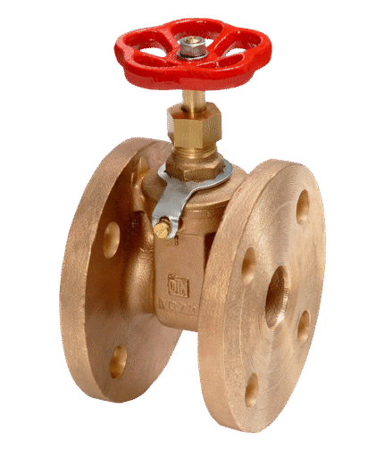
GATE VALVE BRONZE FLANGED DIN 3352 T11
Select options
This product has multiple variants. The options may be chosen on the product page
GATE VALVE CAST IRON FOR DRINKING WATER WITH RUBBER COATED WEDGE F5 DIN EN 1171 (DIN 3352 T2)
Select options
This product has multiple variants. The options may be chosen on the product page
GATE VALVE CAST IRON FOR DRINKING WATER WITH RUBBER WEDGE F4 DIN EN 1171 (DIN 3352 T2)
Select options
This product has multiple variants. The options may be chosen on the product page
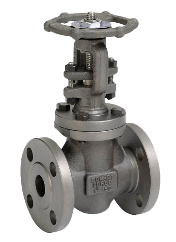
GATE VALVE STEEL WITH RISING STEM F5 DIN
Select options
This product has multiple variants. The options may be chosen on the product page