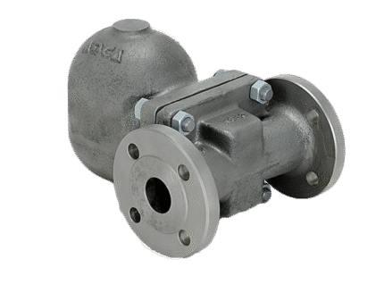
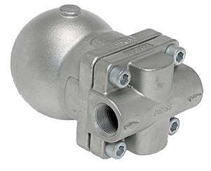
FLOAT FLANGE / THREADED CONDENSATOR SEPARATOR ADCA FLT 14I – DN 25HC
TECHNICAL CHARACTERISTICS
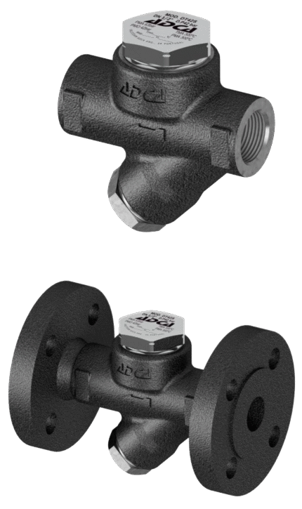
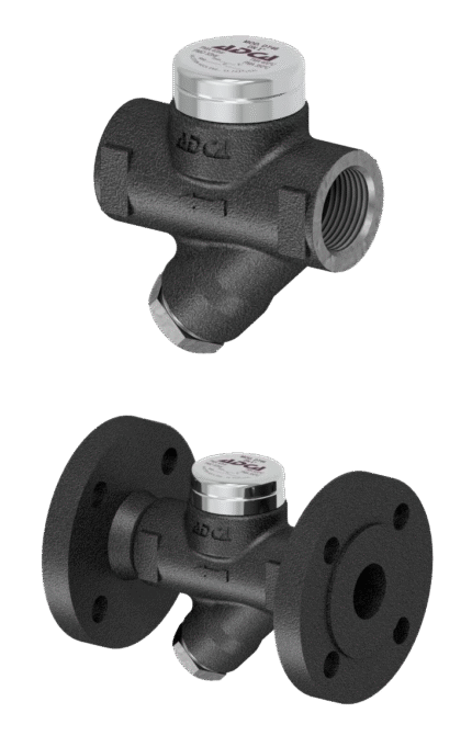
The stainless steel float steam traps model FLT 14I (with thermostatic air vent) are designed to operate over a wide range of operating pressures and can be used in both low and high pressure systems. Typical applications include heaters and heat exchangers, dryers, pressure vessels and applications where continuous condensate drainage is required. Connections are threaded or flanged and horizontal and vertical mounting is possible.
WORKING FLUID / MEDIUM
• Saturated and superheated steam
EXECUTION
• threaded: ISO7/1 Rp (BS21)
• flanged: EN 1092-1 PN16 or ANSI
• models: FLT14I-4,5 , 10 and 14
INSTALLATION INSTRUCTIONS
• In horizontal or vertical position.
MAIN ADVANTAGES
Controlled condensation.
Drainage of condensate at constant temperature.
Not affected by small or large changes in system load and pressure.
Excellent air venting (via thermostatic air vent).
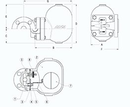
Dimensions: DN 25
Materials
| No. | DETAILS | MATERIALS |
|---|---|---|
| 1 | Body | CF8M / 1.4408 |
| 2 | Lid | CF8M / 1.4408 |
| 3 | Garnish | stainless steel/graphite |
| 4 | Saddle | AISI 410 / 1.4006 |
| 5 | Valve | AISI 440C / 1.4125 |
| 6 | Shoulder | AISI 304 / 1.4301 |
| 7 | Float | AISI 304 / 1.4301 |
| 8 | Thermostatic air vent | stainless steel (bimetallic) |
| 9 | Bolts | stainless steel A2-70 |
Features
| SPECIFICATION | |
|---|---|
| Standard | DIN |
| Joining | flanged EN 1092-1 or ANSI threaded 1" |
| Lid connection | bolted |
| Execution | straight |
| Venting | automatically |
| Installation | horizontal / vertical |
| Maximum differential pressure | 4.5; 10; 14 Bar |
Flow rate
| PASSABILITY (kg/h) | ||||||||||||||
|---|---|---|---|---|---|---|---|---|---|---|---|---|---|---|
| MODEL | SIZE | DIFFERENTIAL PRESSURE (bar) | ||||||||||||
| 0.5 | 1 | 1.5 | 2 | 3 | 4.5 | 6 | 7 | 8 | 9 | 10 | 12 | 14 | ||
| FLT14I - 4.5 | 1”HC - 25HC | 900 | 1250 | 1450 | 1700 | 2010 | 2400 | - | - | - | - | - | - | - |
| FLT14I - 10 | 1”HC - 25HC | 450 | 620 | 790 | 880 | 1100 | 1250 | 1500 | 1600 | 1700 | 1750 | 1800 | - | - |
| FLT14I - 14 | 1”HC - 25HC | 340 | 435 | 530 | 600 | 610 | 850 | 990 | 1100 | 1190 | 1240 | 1300 | 1350 | 1380 |
Limits
| MAXIMUM WORKING CONDITIONS | ||
|---|---|---|
| Maximum working pressure / Bars | T max. [°C] | |
| Flanged PN 16 | Flanged ANSI 150 lb | |
| 16 bar | 16 bar | 100 °C |
| 14.5 bar | 14.8 bar | 150 °C |
| 13.4 bar | 13.6 bar | 200 °C |
| 12.7 bar | 12 bar | 250 °C |
| DIMENSIONS (mm) | ||||||||||||
|---|---|---|---|---|---|---|---|---|---|---|---|---|
| Threaded | Flanged EN PN 16 | Flanged ANSI 150 lb | ||||||||||
| SIZE | A | B | C | D | E | (kg) | F | G | (kg) | F | G | (kg) |
| 1”HC - 25HC | 120 | 195 | 80 | 190 | 110 | 9 | 160 | 248 | 11.3 | 160 | 248 | 10.9 |
Related products
CONDENSATE SEPARATOR FLOAT THREADED / FLANGE ADCA FLT 14I DN 15 – 20
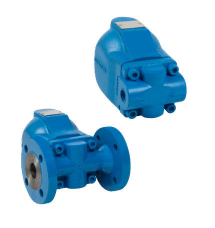
CONDENSATE SEPARATOR FLOAT THREADED / FLANGE ADCA FLT 32
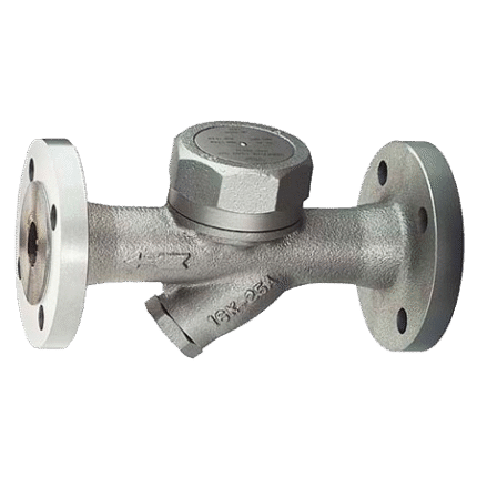
CONDENSATE SEPARATOR THERMODYNAMIC FLANGE TLV AF3N
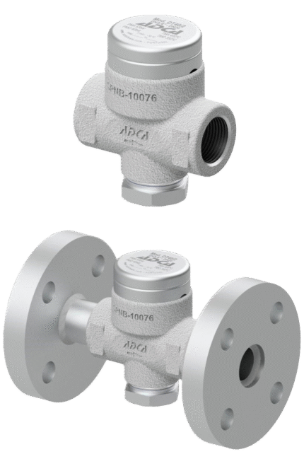
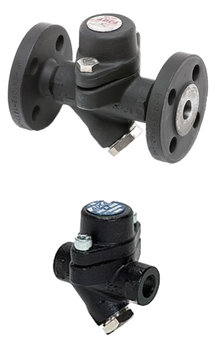
THERMODYNAMIC THREADED / FLANGED CONDENSATE TRAP ADCA DT 40/2
THERMODYNAMIC THREADED / FLANGED CONDENSATE TRAP ADCA DT 42/2
THERMODYNAMIC THREADED / FLANGED CONDENSATE TRAP ADCA DT 46
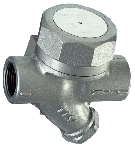
THERMODYNAMIC THREADED CONDENSATE TRAP TLV A3N