
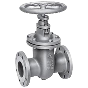
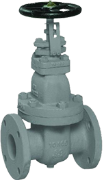
GATE VALVE STEEL WITH NON RISING STEM F4 DIN
TECHNICAL CHARACTERISTICS
Gate valves are primarily intended to stop the flow of fluid. The valve is closed by turning the handwheel clockwise. It is not recommended to use tools to increase the torque of the handwheel during closing and opening of the wedge. The gate valve can only be used in the fully open or closed position. The specified gate valve is not used for flow regulation.
WORKING FLUID / MEDIUM
Steam, water, thermal oil, fuels, lubricating and combustible hydraulic oils, petroleum, air, gas, non-combustible hydraulic fluids, boiler feed water, condensate, seawater.
Dimensions: DN 40 – 600
Additional information
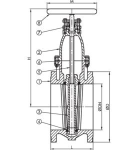
Materials
| No. | DETAILS | MATERIALS |
|---|---|---|
| 1 | Body | steel GP240GH / 1.0619 / GSC25 |
| 2 | Cover | steel GP240GH / 1.0619 / GSC25 |
| 3 | Wedge | ASTM A479 410 |
| 4 | Seat | ASTM A 479 410 + stellite |
| 5 | Stem | ASTM A479 410 |
| 6 | Cover seal | metal-graphite |
| 7 | Gland seal | graphite packing |
| 8 | Flywheel | steel 1.0619 |
Features
| SPECIFICATION | |
|---|---|
| Connection | EN 1092-1 |
| Construction length | EN 558, series 14 |
| Cover connection | bolted |
| Execution | straight |
| Connection | flanged |
| Operation | manually with wheel |
| Actuation | multi-turn |
| T max. °C | 350 °C |
Dimensions
| DN | PN | Flanges/PN | L | D | ØP* | nxd | H | kg | |||
|---|---|---|---|---|---|---|---|---|---|---|---|
| range | PN10 | PN16 | PN10 | PN16 | PN10 | PN16 | |||||
| 40 | PN 16 | PN16 | 140 | 150 | 150 | 110 | 110 | 4x18 | 4x18 | 230 | 15.0 |
| 50 | PN 16 | PN16 | 150 | 165 | 165 | 125 | 125 | 4x18 | 4x18 | 235 | 17.0 |
| 65 | PN 16 | PN16 | 170 | 185 | 185 | 145 | 145 | 4x18 | 4x18 | 260 | 20.0 |
| 80 | PN 16 | PN16 | 180 | 200 | 200 | 160 | 160 | 8x18 | 8x18 | 285 | 27.0 |
| 100 | PN 16 | PN16 | 190 | 220 | 220 | 180 | 180 | 8x18 | 8x18 | 34.0 | |
| 125 | PN 16 | PN16 | 200 | 250 | 250 | 210 | 210 | 8x18 | 8x18 | 50.0 | |
| 150 | PN 16 | PN16 | 210 | 285 | 285 | 240 | 240 | 8x23 | 8x23 | 60.0 | |
| 200 | PN 10 | PN16 | 230 | 340 | 340 | 295 | 295 | 12x23 | 12x23 | 100.0 | |
| 250 | PN 10 | PN10/16 | 250 | 395 | 405 | 350 | 355 | 12x23 | 12x26 | 165.0 | |
| 300 | PN 10 | PN10/16 | 270 | 445 | 460 | 400 | 410 | 12x23 | 12x30 | 220.0 | |
| 350 | PN 10 | PN10/16 | 290 | 505 | 520 | 460 | 470 | 16x26 | 16x30 | 250 | |
| 400 | PN 10 | PN10/16 | 310 | 565 | 580 | 515 | 525 | 16x26 | 16x30 | 292 | |
| 500 | PN 10 | PN10/16 | 350 | 670 | 715 | 620 | 650 | 20x26 | 20x33 | 380 | |
| 600 | PN 10 | PN10/16 | 390 | 780 | 840 | 725 | 770 | 20x30 | 20x36 | 490 | |
| Note: The dimensions in column ØP should be considered as the diameters of the bolt circle, as the latter are not indicated in the drawing. | |||||||||||
Related products
Select options
This product has multiple variants. The options may be chosen on the product page
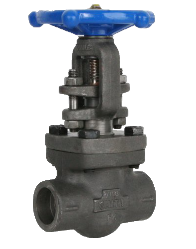
FORGED GATE VALVE CARBON STEEL WITH RISING STEM SW / 800 LBS
Select options
This product has multiple variants. The options may be chosen on the product page
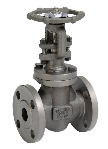
FORGED GATE VALVE STEEL WITH RISING STEM SW / 150 LBS
Select options
This product has multiple variants. The options may be chosen on the product page
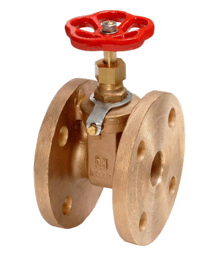
GATE VALVE BRONZE FLANGED DIN 3352 T11
Select options
This product has multiple variants. The options may be chosen on the product page
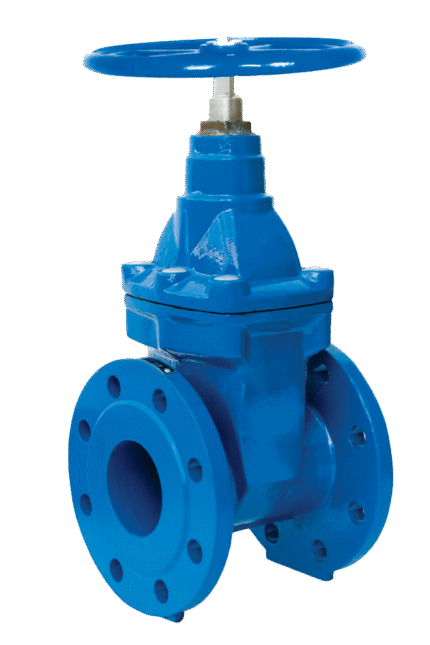
GATE VALVE CAST IRON FOR DRINKING WATER WITH RUBBER WEDGE F4 DIN EN 1171 (DIN 3352 T2)
Select options
This product has multiple variants. The options may be chosen on the product page
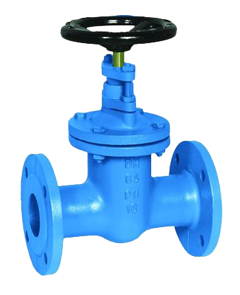
GATE VALVE CAST IRON NON RISING STEM F5 DIN EN 1171 (DIN 3352 T2)
Select options
This product has multiple variants. The options may be chosen on the product page
GATE VALVE JIS 5K JIS F7400 CAST IRON WITH NON RISING STEM AND POSITION INDICATOR
Select options
This product has multiple variants. The options may be chosen on the product page
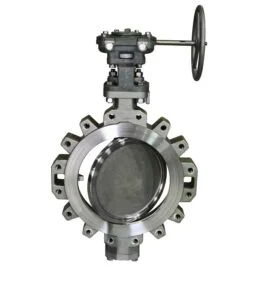
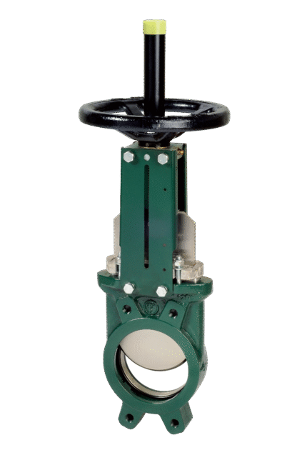
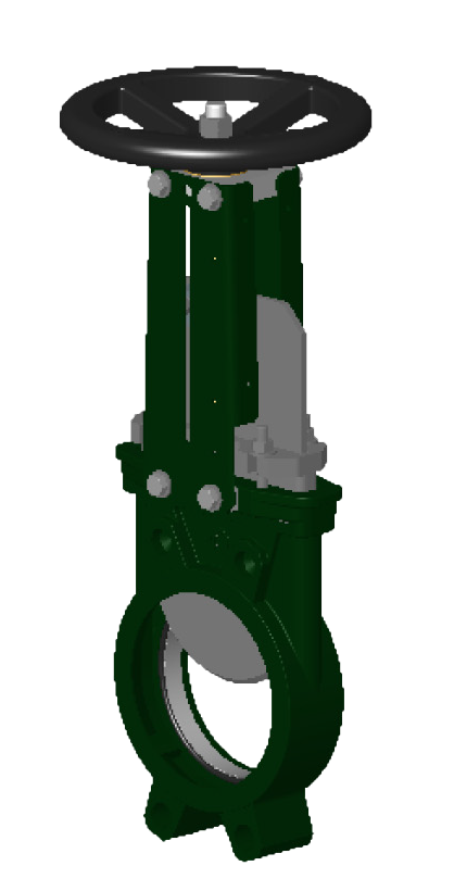
KNIFE GATE VALVE CAST IRON VG3400-00 RISING SPINDLE DIN PN 10-16
Select options
This product has multiple variants. The options may be chosen on the product page