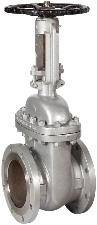
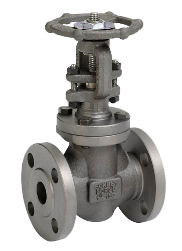
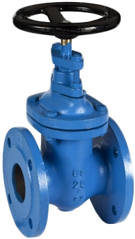
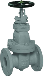
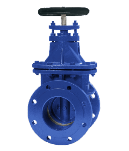
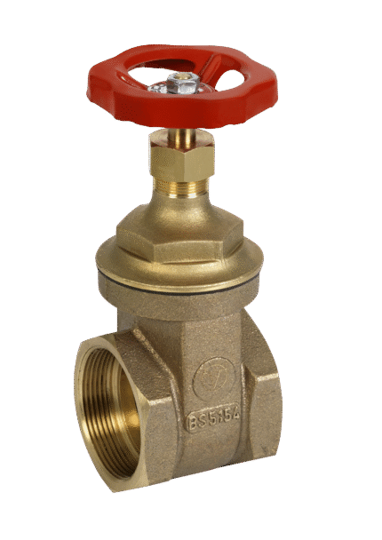
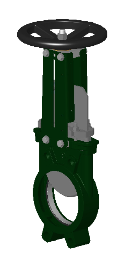
GATE VALVE STEEL WITH RISING STEM F4 DIN
TECHNICAL CHARACTERISTICS
Gate valves are primarily intended to stop the flow of fluid. The valve is closed by turning the handwheel clockwise. It is not recommended to use tools to increase the torque of the handwheel during closing and opening of the wedge. The gate valve can only be used in the fully open or closed position. The specified gate valve is not used for flow regulation.
WORKING FLUID / MEDIUM
Steam, water, thermal oil, fuels, lubricating and combustible hydraulic oils, petroleum, air, gas, non-combustible hydraulic fluids, boiler feed water, condensate, seawater.
Dimensions: DN 40 – 700
Този продукт вече е в списъка ви със заявки за оферта. (This product is already in your quote request list.)
Additional information
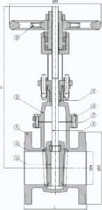
Materials
| No. | DETAILS | MATERIALS |
|---|---|---|
| 1 | Body | steel GP240GH 1.0619 GSC25 |
| 2 | Cover | steel GP240GH 1.0619 GSC25 |
| 3 | Wedge | steel GP240GH 1.0619 GSC25 |
| 4 | Seat | stainless steel X5CrNi18-10 (1.4301) |
| 5 | Stem | stainless steel X20Cr13 (1.4021) |
| 6 | Cover seal | metal graphite |
| 7 | Gland seal | graphite packing |
| 8 | Handwheel | cast iron EN-GJL250, EN-JL 1040 |
Features
| SPECIFICATION | |
|---|---|
| Standard | DIN 3352 T3 |
| Connection | DIN flanges EN 1092-1/B |
| Construction length | EN 558 series 14 (DIN 3202 F4) |
| Cover connection | bolted |
| Execution | straight |
| Opperation | manually with wheel |
| Actuation | multi-turn |
| T max. °C | 350 °C |
Dimensions
| DN | PN | Flanges/PN | L | D | ØP* | nxd | H | R | Weight (kg) | |||
|---|---|---|---|---|---|---|---|---|---|---|---|---|
| PN10 | PN16 | PN10 | PN16 | PN10 | PN16 | |||||||
| 40 | PN 16 | PN16 | 140 | 150 | 110 | 4x18 | 230 | 140 | 15.0 | |||
| 50 | PN 16 | PN16 | 150 | 165 | 125 | 4x18 | 235 | 140 | 17.0 | |||
| 65 | PN 16 | PN16 | 170 | 185 | 145 | 4x18 | 260 | 160 | 20.0 | |||
| 80 | PN 16 | PN16 | 180 | 200 | 160 | 8x18 | 285 | 160 | 27.0 | |||
| 100 | PN 16 | PN16 | 190 | 220 | 180 | 8x18 | 320 | 200 | 34.0 | |||
| 125 | PN 16 | PN16 | 200 | 250 | 210 | 8x18 | 395 | 200 | 50.0 | |||
| 150 | PN 16 | PN16 | 210 | 285 | 240 | 8x23 | 435 | 200 | 60.0 | |||
| 200 | PN 10 | PN16 | 230 | 340 | 295 | 12x23 | 555 | 250 | 100.0 | |||
| 250 | PN 10 | PN10/16 | 250 | 395 | 405 | 350 | 355 | 12x23 | 12x26 | 645 | 315 | 165.0 |
| 300 | PN 10 | PN10/16 | 270 | 445 | 460 | 400 | 410 | 12x23 | 12x30 | 1160 | 500 | 220.0 |
| 350 | PN 6 | PN10/16 | 290 | 505 | 520 | 460 | 470 | 16x26 | 16x30 | 1305 | 500 | 250 |
| 400 | PN 6 | PN10/16 | 310 | 565 | 580 | 515 | 525 | 16x26 | 16x30 | 1405 | 640 | 292 |
| 500 | PN 6 | PN10/16 | 350 | 670 | 715 | 620 | 650 | 20x26 | 20x33 | 1785 | 720 | 530 |
| 600 | PN 4 | PN10/16 | 390 | 780 | 840 | 725 | 770 | 20x30 | 20x36 | 1935 | 720 | 640 |
| 700 | PN 4 | PN10/16 | 430 | 895 | 910 | 840 | 840 | 24x30 | 24x36 | 2200 | 800 | 830 |
| Note: The dimensions in column ØP should be considered as the diameters of the bolt circle, as the latter are not indicated in the drawing. | ||||||||||||

