
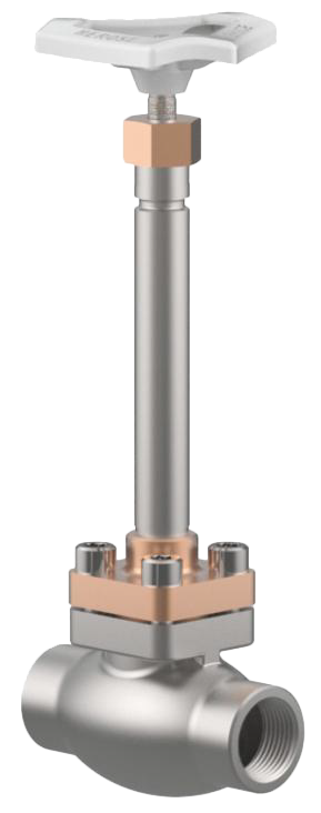
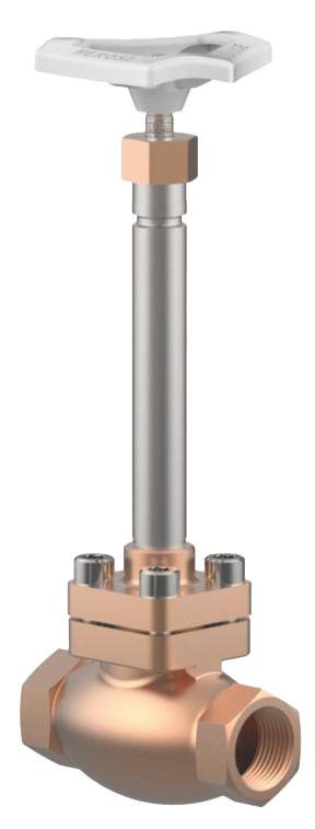
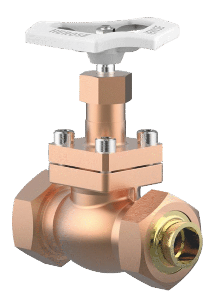
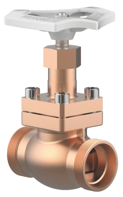
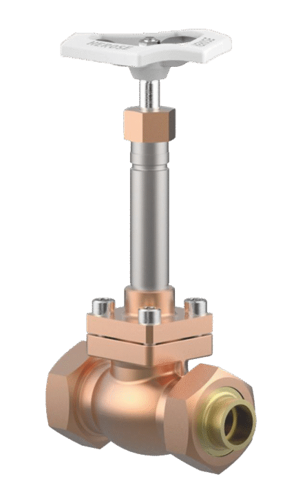
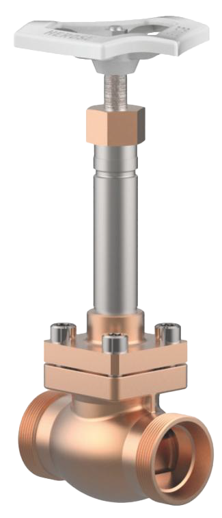
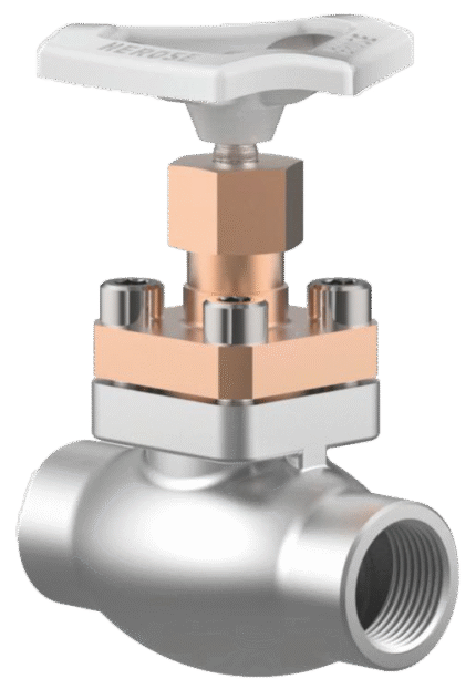
CRYOGENIC GATE VALVE TYPE 01331 WELDED
TECHNICAL DESCRIPTION
Cryogenic shut-off and check valves, PN50 (DN150=PN40)
· stainless steel body and bronze bonnet · pre-stressed gland · cleaned and degreased for oxygen service Butt weld ends acc. to ISO 1127 and ASTM A312: · Part No. 01331.X.000* Valves · Part No. 01331.X.500* Check valves Welding sockets acc. to ISO 1127 and ASTM A312: · Part No. 01331.X.0004 Valve · Part No. 01331.X.5004 Check valves <span style=”font-weight:800;”>WORKING FLUID / MEDIUM</span>
Approved for gases, vapors and liquefied cryogenic gases and LNG.
OPTIONS
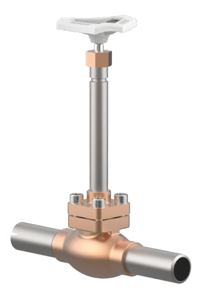
· welded sleeves for stainless steel pipes according to ISO 1127 and ASTM A312 – length FF + 200mm · regulating valve (with threaded connection) · wall thickness of extension pipes
Dimensions: DN 10 – 100
Additional information
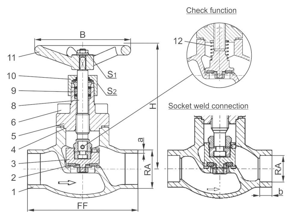
Materials
| No. | Materials | DIN EN | ASTM |
|---|---|---|---|
| 1 | Body | 1.4308 | A351CF8 |
| 2 | Saddle up to DN50 | Teflon PTFE / graphite filler (25%) | |
| 2a | DN65 saddle | Teflon PTFE | |
| 3 | Valve | brass CW614N | B283 UNS C38500 |
| 4 | Lid gasket | Teflon PTFE | |
| 5 | Upper part | CC493K | B505 UNS C93200 |
| 6 | Bolts | 1.4301/A2 | A 194 B8 |
| 8 | Spindle | 1.4301 | A276 type 304 |
| 9 | Salnikov condensed. | graphite / Teflon PTFE | |
| 10 | Packing nut | brass CW614N | B283 UNS C38500 |
| 11 | Flywheel | aluminum alloy | |
| 12 | Spring | CW452K | B159 UNS C51900 |
Features
| SPECIFICATION | |
|---|---|
| Type 01331 | valve/return valve PN 50 (DN150=PN40) |
| Connection ends | for forehead welding |
| Construction length | construction normal |
| Attaching the lid | flanged |
| Execution | straight |
| Joining | on a weld |
| Drive | manually |
| Working temp. [°C] | -196 °C / -321 °F |
| +120 °C / +248 °F | |
| Recommended temp. [°C] | -60°C / -76°F |
| +120 °C / +248 °F | |
Dimensions
| DN | Size code (X.) | Construction length (FF) | Height (H) | Pipe Ø ISO 1127 (RA) | Wall thickness ISO 1127 (a) | OD pipe Ø ASTM A312 (RA) | Wall thickness ASTM A312 (a) | Socket depth (b) | Flywheel Ø (B) | Hex size (S1) | Hex size (S2) | Weight (kg) | Kvs (m³/h) | Cv (gal/min) |
|---|---|---|---|---|---|---|---|---|---|---|---|---|---|---|
| 10 | 1012 | 70 | 140 | 12.0 | 1.0 | 13.72 | S10 or S40 | 6 | 100 | 7 | 30 | 1.0 | 1.6 | 1.9 |
| 15 | 1517 | 85 | 140 | 17.2 | 1.6 | 17.15 | S10 or S40 | 10 | 100 | 7 | 30 | 1.25 | 3.8 | 4.4 |
| 15 | 1521 | 85 | 140 | 21.3 | 2.0 | 21.34 | S10 or S40 | 10 | 100 | 7 | 30 | 1.3 | 4.3 | 5.0 |
| 20 | 2026 | 100 | 140 | 26.9 | 2.0 | 26.67 | S10 or S40 | 13 | 100 | 7 | 30 | 1.7 | 6.7 | 7.8 |
| 25 | 2533 | 115 | 140 | 33.7 | 2.0 | 33.40 | S10 or S40 | 13 | 100 | 7 | 30 | 2.0 | 11.5 | 13.4 |
| 32 | 3238 | 115 | 170 | 38.0 | 2.0 | - | S10 or S40 | - | 125 | 10 | 36 | 2.8 | 14.0 | 16.2 |
| 40 | 4042 | 130 | 175 | 42.4 | 2.0 | 42.16 | S10 or S40 | 13 | 125 | 10 | 36 | 4.2 | 20.6 | 23.9 |
| 40 | 4048 | 130 | 175 | 48.3 | 2.0 | 48.26 | S10 or S40 | 13 | 125 | 10 | 36 | 4.2 | 22.6 | 26.3 |
| 50 | 5060 | 155 | 200 | 60.3 | 2.0 | 60.32 | S10 or S40 | 16 | 125 | 10 | 36 | 6.7 | 37.1 | 43.2 |
| 65 | 657x | 205 | 260 | 76.1 | 2.6 | 73.02 | S10 or S40 | 16 | 200 | 10 | 36 | 10.7 | 71.1 | 82.7 |
| 80 | 8088 | 245 | 310 | 88.9 | 3.2 | 88.90 | S10 or S40 | 16 | 250 | 10 | 36 | 16.0 | 104.0 | 120.9 |
| 100 | 0114 | 280 | 350 | 114.3 | 6.0 | 114.30 | S10 or S40 | 20 | 315 | 12 | 41 | 22.0 | 170.0 | 195.2 |
| 150 | 0168 | 400 | 420 | 168.3 | 7.1 | 168.27 | S10 or S40 | 20 | 360 | 15 | 41 | 54.1 | 350.0 | 401.8 |
Related products
Select options
This product has multiple variants. The options may be chosen on the product page
CRYOGENIC GATE VALVE TYPE 01301 ON WELDED JOINT
Select options
This product has multiple variants. The options may be chosen on the product page
CRYOGENIC GATE VALVE TYPE 01311 WITH EXTENDED SPINDLE AND BRAZED STAINLESS STEEL ENDS
Select options
This product has multiple variants. The options may be chosen on the product page
CRYOGENIC GATE VALVE TYPE 01315 WITH EXTENDED THREADED SPINDLE
Select options
This product has multiple variants. The options may be chosen on the product page
CRYOGENIC GATE VALVE TYPE 02401 ON HOLLAND CONNECTOR WITH BRASS SOLDERING FITTINGS
Select options
This product has multiple variants. The options may be chosen on the product page
CRYOGENIC GATE VALVE TYPE 02401 WITH FLANGE CONNECTION
Select options
This product has multiple variants. The options may be chosen on the product page
CRYOGENIC GATE VALVE TYPE 02411 WITH EXTENDED SPINDLE OF JOINT WITH BRASS SOLDERING FITTINGS
Select options
This product has multiple variants. The options may be chosen on the product page
CRYOGENIC GATE VALVE TYPE 02411 WITH EXTENDED SPINDLE ON FLANGE CONNECTION
Select options
This product has multiple variants. The options may be chosen on the product page