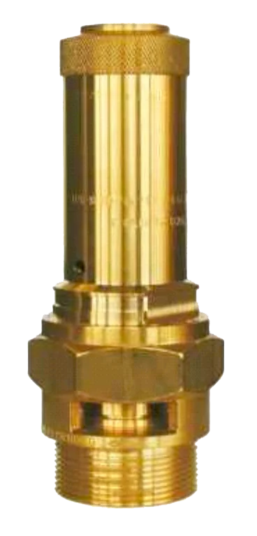
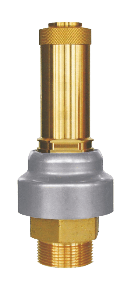
BRASS PROPORTIONAL SAFETY VALVE THREADED HEROSE 06205
TECHNICAL DESCRIPTION
Automatic safety valve, opening proportionally to pressure rise. The constant force between the pressure force and the reaction of the closing spring ensures a minimum flow, respectively fluid consumption when the valve is actuated. Full opening, at 10% overpressure of the valve setting. When ordering a valve, please inform us of your requirements regarding valve capacity, fluid type, temperature, inlet size and the type of system in which it will be used. Standard safety valve with FPM seat seal, open bonnet with unloading windows and forced opening device. Thread type G (BSPP) according to ISO 228/1 Used as a safety device in the event of excessive pressure rise in stationary systems and mobile gas cylinders and pressure vessels. Suitable for air and similar gases. Operating temperature: -20°C / -4°F (253K) up to +160°C / +320°F (433K), size d07 also suitable for horizontal installation.
WORKING FLUID / MEDIUM
Liquids, gases, steam.
EXECUTION
Only upon request:
- stainless sealing ring – stainless steel 1.4571.
- external nickel coating on the valve.
Dimensions: DN 1/2″ – 1 1/4″
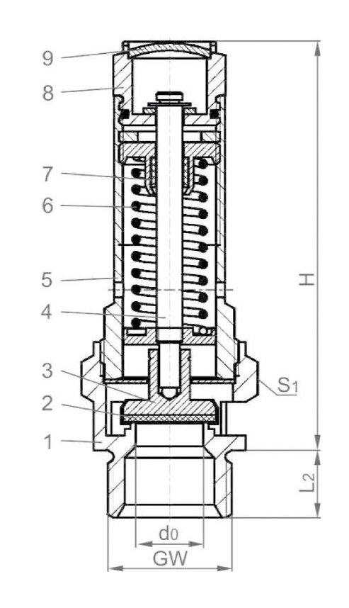
Materials
| No. | DETAILS | MATERIALS |
|---|---|---|
| 1 | Body | CW614N B249 UNS C38500 |
| 2 | Saddle | FPM (Viton) |
| 3 | Valve | CW614N B249 UNS C38500 |
| 4 | Spindle | CW614N B249 UNS C38500 |
| 5 | Lid | CW614N B249 UNS C38500 |
| 6 | Spring | 1.1200 A 227 |
| 7 | Spindle guide | Teflon/PTFE |
| 8 | Lifting device. | CW614N B249 UNS C38500 |
| 9 | Closing cap | CW507L B36 UNS C2680 |
Features
| SPECIFICATION | |
|---|---|
| Lid connection | threaded |
| Execution | straight |
| Joining | male thread (BSPP) |
| Management | automatic/(forced) |
| Operating temperature range | -20°C / -4°F (253K) to +160°C / +320°F (433K) |
Capacity
| PASSABILITY | |||||||||
|---|---|---|---|---|---|---|---|---|---|
| P set. | GW | 1/4 | 3/8 | 1/2 | 1/2 | 3/4 | 1 | 1-1/4 | |
| bar (g) | to (mm): | 7.0 | 7.0 | 7.0 | 12.0 | 15.0 | 18.0 | 20.0 | |
| Ao (mm²): | 38.48 | 38.48 | 38.48 | 113.1 | 176.7 | 254.5 | 314.2 | ||
| Fluid: | air in m³/h at 0 °C and 1013.25 mbar | ||||||||
| 0.2 | - | - | - | 30 | 60 | 86 | 106 | ||
| 0.4 | 19 | 19 | 19 | 42 | 84 | 121 | 150 | ||
| 0.6 | 23 | 23 | 23 | 52 | 104 | 150 | 186 | ||
| 0.8 | 28 | 28 | 28 | 61 | 124 | 178 | 220 | ||
| 1.0 | 32 | 32 | 32 | 70 | 142 | 205 | 253 | ||
| 2.0 | 50 | 50 | 50 | 113 | 239 | 345 | 426 | ||
| 3.0 | 67 | 67 | 67 | 156 | 327 | 472 | 582 | ||
| 4.0 | 85 | 85 | 85 | 196 | 411 | 592 | 731 | ||
| 5.0 | 102 | 102 | 102 | 236 | 496 | 714 | 881 | ||
| 6.0 | 120 | 120 | 120 | 276 | 579 | 834 | 1030 | ||
| 7.0 | 137 | 137 | 137 | 316 | 663 | 955 | 1179 | ||
| 8.0 | 155 | 155 | 155 | 357 | 749 | 1079 | 1332 | ||
| 9.0 | 172 | 172 | 172 | 398 | 833 | 1200 | 1482 | ||
| 10.0 | 190 | 190 | 190 | 439 | 919 | 1324 | 1634 | ||
| 11.0 | 206 | 206 | 206 | 475 | 994 | 1432 | 1768 | ||
| 12.0 | 225 | 225 | 225 | 519 | 1087 | 1566 | 1934 | ||
| 14.0 | 260 | 260 | 260 | 599 | 1256 | 1809 | 2233 | ||
| 16.0 | 295 | 295 | 295 | 680 | 1424 | 2051 | 2532 | ||
| 18.0 | 330 | 330 | 330 | 760 | - | 2294 | - | ||
| 20.0 | 368 | 368 | 368 | 849 | - | - | - | ||
| 22.0 | 404 | 404 | 404 | 930 | - | - | - | ||
| 25.0 | 457 | 457 | 457 | - | - | - | - | ||
| 27.0 | 492 | 492 | 492 | - | - | - | - | ||
| 30.0 | 550 | 550 | 550 | - | - | - | - | ||
| 32.0 | 585 | 585 | 585 | ||||||
| 34.0 | 621 | 621 | 621 | ||||||
| 36.0 | 657 | 657 | 657 | ||||||
| 38.0 | 692 | 692 | 692 | ||||||
| 40.0 | 734 | 734 | 734 | ||||||
| 42.0 | 770 | 770 | 770 | ||||||
| 43.0 | 788 | 788 | 788 | ||||||
| The stated throughput is measured with the valve fully open. | |||||||||
| DN | Cross-section | Frame code | Pressure setting | Height | Length | Key size | Weight | Permeability coefficient at 3.0 bar |
|---|---|---|---|---|---|---|---|---|
| GW | do | .X. | bar | H | L2 | S1 | approx. kg | αw |
| 1/4 | 7 | 200 | 0.4-43 | 60 | 10 | 21 | 0.07 | 0.6 |
| 3/8 | 7 | 300 | 0.4-43 | 60 | 10 | 21 | 0.07 | 0.6 |
| 1/2 | 7 | 704 | 0.4-43 | 67 | 12 | 24 | 0.17 | 0.6 |
| 1/2 | 12 | 400 | 0.2-22 | 78 | 12 | 27 | 0.17 | 0.47 |
| 3/4 | 15 | 600 | 0.2-16 | 92 | 15 | 32 | 0.27 | 0.63 |
| 1 | 18 | 1000 | 0.2-18 | 110 | 18 | 41 | 0.48 | 0.63 |
| 1-1/4 | 20 | 1200 | 0.2-16 | 125 | 20 | 48 | 0.75 | 0.63 |
Related products
BRASS PROPORTIONAL SAFETY VALVE THREADED HEROSE 06205
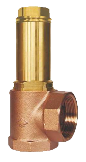
BRONZE PROPORTIONAL SAFETY VALVE THREADED HEROSE 06195
BRONZE PROPORTIONAL SAFETY VALVE THREADED HEROSE 06380
BRONZE PROPORTIONAL SAFETY VALVE THREADED HEROSE 06505

CAST IRON FULL-LIFT SAFETY VALVE DIN THREADED
STAINLESS STEEL FULL-LIFT SAFETY VALVE DIN THREADED
STAINLESS STEEL FULL-LIFT SAFETY VALVE FLANGED DIN