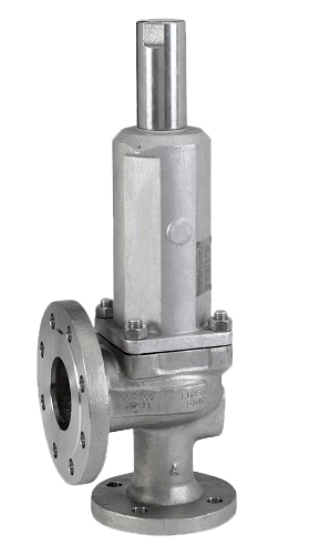
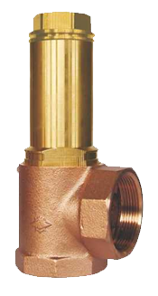
BRONZE PROPORTIONAL SAFETY VALVE THREADED HEROSE 06505
TECHNICAL DESCRIPTION
It is used as a safety device in case of excessive pressure increase in portable gas cylinders and pressure vessels. Suitable for liquids, granulates and powdery materials.
PRINCIPLE OF OPERATION
Automatic safety valve that opens proportionally to pressure rise. The constant force between the pressure force and the reaction of the closing spring ensures minimal flow, respectively minimal fluid loss when the valve is actuated.
WORKING FLUID / MEDIUM
Liquids, granules and powders
TECHNICAL DESCRIPTION
Standard safety valve with FPM seat seal, closed bonnet with relief windows and positive opening device. Male thread type G (BSPP) according to ISO 228/1
OPTIONS
Possible options upon request:
• nickel plating on the external parts
Dimensions:DN 1″ – 2″
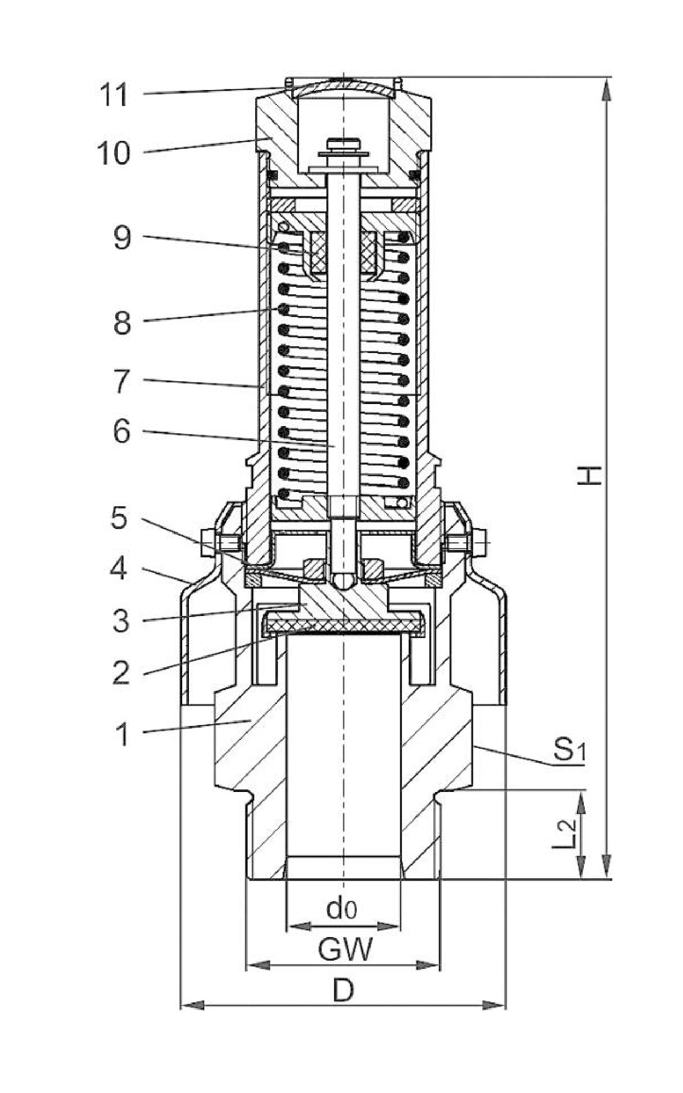
Materials
| No. | DETAILS | MATERIALS |
|---|---|---|
| 1 | Body | CW617N B283 UNS C37700 |
| 2 | Saddle seal | FPM (Viton - GLT) |
| 3 | Valve | CW614N B455 UNS C38500 |
| 4 | Protective cap | 1.4301 A240 Grade 304 |
| 5 | Diaphragm | silicone |
| 6 | Spindle | CW614N B249 UNS C38500 |
| 7 | Lid | CW614N B249 UNS C38500 |
| 8 | Spring | 1.4571 / A313 Grade 316 Ti |
| 9 | Spindle guide | Teflon/PTFE |
| 10 | Lifting device | CW614N B455 UNS C38500 |
| 11 | Cap | CW507L / ASTM - B 36 UNS C26800 |
Features
| SPECIFICATION | |
|---|---|
| Lid connection | threaded |
| Execution | angular |
| Joining | thread |
| Management | automatically |
| Operating temperature | -40°C / -40°F (233K) to +200°C / +392°F (473K) |
Capacity
| PASSABILITY | |||||||||||||
|---|---|---|---|---|---|---|---|---|---|---|---|---|---|
| P adjustable | GW: | 1 | 1-1/4 | 1-1/2 | 1-1/4 | 1-1/2 | 2 | ||||||
| bar (g) | d₀ (mm): | 24.0 | 28.0 | 28.0 | 31.0 | 31.0 | 48.0 | ||||||
| A₀ (mm²): | 452.4 | 615.8 | 615.8 | 754.8 | 754.8 | 1810.0 | |||||||
| Fluid: | air in m³/h at 0 °C and 1013.25 mbar | ||||||||||||
| 0.5 | 237 | 297 | 297 | 435 | 435 | 835 | |||||||
| 0.6 | 268 | 326 | 326 | 482 | 482 | 949 | |||||||
| 0.7 | 299 | 354 | 354 | 535 | 535 | 1063 | |||||||
| 0.8 | 329 | 392 | 392 | 579 | 579 | 1153 | |||||||
| 0.9 | 353 | 422 | 422 | 631 | 631 | 1240 | |||||||
| 1.0 | 372 | 449 | 449 | 673 | 673 | 1250 | |||||||
| 1.2 | 414 | 508 | 508 | 759 | 759 | 1390 | |||||||
| 1.4 | 456 | 578 | 578 | 848 | 848 | 1531 | |||||||
| 1.6 | 504 | 639 | 639 | 941 | 941 | 1675 | |||||||
| 1.8 | 553 | 703 | 703 | 1031 | 1031 | 1863 | |||||||
| 2.0 | 604 | 768 | 768 | 1123 | 1123 | 2059 | |||||||
| 2.2 | 648 | 825 | 825 | 1200 | 1200 | 2243 | |||||||
| 2.4 | 694 | 883 | 883 | 1277 | 1277 | 2431 | |||||||
| 2.6 | 740 | 942 | 942 | 1354 | 1354 | 2546 | |||||||
| 2.8 | 782 | 995 | 995 | 1431 | 1431 | 2657 | |||||||
| 3.0 | 825 | 1051 | 1051 | 1511 | 1511 | 2770 | |||||||
| 3.2 | 868 | 1105 | 1105 | 1588 | 1588 | 3024 | |||||||
| 3.4 | 910 | 1158 | 1158 | 1665 | 1665 | 3170 | |||||||
| 3.5 | 931 | 1185 | 1185 | 1628 | 1628 | 3244 | |||||||
| 3.6 | 952 | 1212 | 1212 | 1665 | 1665 | - | |||||||
| 3.8 | 994 | 1266 | 1266 | 1739 | 1739 | - | |||||||
| 4.0 | 1036 | 1319 | 1319 | 1812 | 1812 | - | |||||||
| 4.2 | 1078 | 1373 | 1373 | 1886 | 1886 | - | |||||||
| 4.4 | 1120 | 1427 | 1427 | 1960 | 1960 | - | |||||||
| 4.5 | 1049 | 1453 | 1453 | 1997 | 1997 | - | |||||||
| 4.6 | 1069 | - | - | 2034 | 2034 | - | |||||||
| 4.8 | 1107 | - | - | 2107 | 2107 | - | |||||||
| 5.0 | 1148 | - | - | 2185 | 2185 | - | |||||||
| 5.2 | 1187 | - | - | 2259 | 2259 | - | |||||||
| 5.4 | 1226 | - | - | 2333 | 2333 | - | |||||||
| 5.6 | 1265 | - | - | 2407 | 2407 | - | |||||||
| 5.8 | 1304 | - | - | 2481 | 2481 | - | |||||||
| 6.0 | 1343 | - | - | 2555 | 2555 | - | |||||||
| The stated throughput is measured with the valve fully open. | |||||||||||||
| DN | Hole | Size code | Setting range | Diameter of the protective cap | Key | Weight, kg | Permeability coefficient at 3 Bar | Permeability coefficient at 3.5 Bar | Permeability coefficient at 4.5 Bar | ||
|---|---|---|---|---|---|---|---|---|---|---|---|
| GW | d₀ | .X. | Bar | H | L₂ | S₁ | kg | aᵥᵥ | aᵥᵥ | aᵥᵥ | |
| 1" | 24 | 1000 | 0.5-0.6 | 194 | 18 | 80 | 55 | 1.75 | 0.62 | 0.57 | |
| 1 1/4" | 28 | 2812 | 0.5-4.5 | 198 | 22 | 80 | 55 | 1.85 | 0.58 | ||
| 1 1/2" | 28 | 2814 | 0.5-4.5 | 198 | 22 | 80 | 55 | 1.9 | 0.58 | ||
| 1 1/4" | 31 | 3112 | 0.5-0.6 | 191 | 22 | 80 | 55 | 2 | 0.68 | 0.65 | |
| 1 1/2" | 31 | 3114 | 0.5-0.6 | 191 | 22 | 80 | 55 | 2.3 | 0.68 | 0.65 | |
| 2" | 48 | 2000 | 0.5-3.5 | 232 | 25 | 115 | 85 | 4.5 | 0.52 |
Related products
BRASS PROPORTIONAL SAFETY VALVE THREADED HEROSE 06205
BRASS PROPORTIONAL SAFETY VALVE THREADED HEROSE 06205
BRONZE PROPORTIONAL SAFETY VALVE THREADED HEROSE 06195
BRONZE PROPORTIONAL SAFETY VALVE THREADED HEROSE 06216 / 06217
BRONZE PROPORTIONAL SAFETY VALVE THREADED HEROSE 06370
BRONZE PROPORTIONAL SAFETY VALVE THREADED HEROSE 06380
CAST IRON FULL-LIFT SAFETY VALVE DIN THREADED