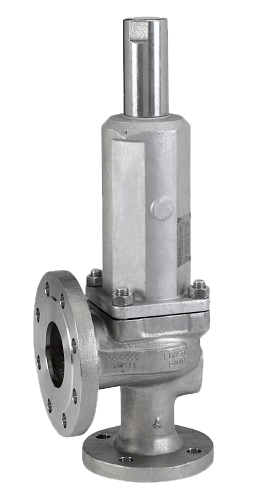
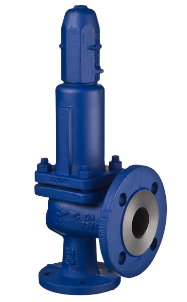
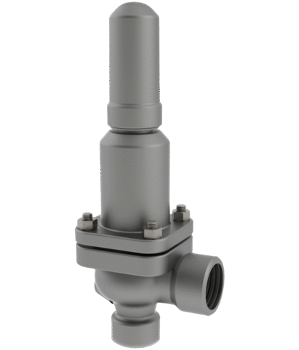
TOSACA THREADED SAFETY VALVES MODEL 1400
TECHNICAL DESCRIPTION
SAFETY OVERFLOW VALVES TOSACA MODEL 1400
• Dimensioning – EN-4126-1 / 7
• Structural design EN-12516-1, EN-4126-1 / 7
• Materials – EN / ASTM
• Tests – EN-4126-1 / 7, MSS-SP-55
• Tolerances EN-4126-1 and ASME UG-126
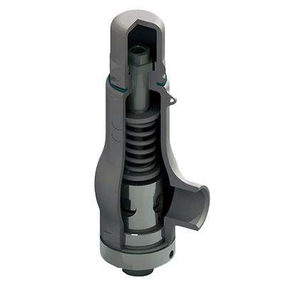
PRINCIPLE OF OPERATION
Automatic safety valve that opens proportionally to pressure rise.
The constant force between the pressure force and the reaction of the closing spring ensures minimal flow, respectively minimal fluid loss when the valve is actuated.
WORKING FLUID / MEDIUM
Steam, gases, gas vapors and liquids
OPTIONS
• Available body materials: ductile iron, carbon steel, stainless steel, LCC, duplex and super duplex steels
• Available seat sealing materials: metal/metal, PTFE, Viton and Stellite
Upon request
Dimensions: DN 15 – 400

Materials
| No. | Description | 15 x 25 to 25 x 40 PN16/25 steel | 32 x 50 to 400 x 500 PN16/25 ductile iron | 15 x 25 to 400 x 500 PN40-100 steel |
15 x 25 to 400 x 500 PN 16-100 stainless steel |
|---|---|---|---|---|---|
| 1 | Nozzle | AISI-316L | A351 CF-8 | A351 CF-8 | A351 CF-8 |
| 2 | Body | CS 1.0619 | EN-JS1030 | CS 1.0619 | 1.4409 |
| 3 | Lid | CS 1.0619 | EN-JS1030 | CS 1.0619 | 1.4409 |
| 4 | Cap | A351 CF-8 | A351 CF-8 | A351 CF-8 | A351 CF-8 |
| 5 | Valve | AISI-316L | AISI-316L | AISI-316L | AISI-316L |
| 6 | Driver | AISI-304 | AISI-304 | AISI-304 | AISI-304 |
| 7 | Drive rod | AISI-316L | AISI-316L | AISI-316L | AISI-316L |
| 8 | Button | Steel | Steel | Steel | AISI-303 |
| 9 | Adjustment screw | AISI-303 | AISI-303 | AISI-303 | AISI-303 |
| 10 | Lock nut | AISI-303 | AISI-303 | AISI-303 | AISI-303 |
| 11 | Spring | 1.8159 steel | 1.8159 steel | 1.8159 steel | AISI-302 |
| 12 | Handle | A 351 CF 8 | A 351 CF 8 | A 351 CF 8 | A351 CF-8 |
| 17 | Nut | AISI-304 | AISI-304 | AISI-304 | AISI-304 |
| 18 | Axis | AISI-303 | AISI-303 | AISI-303 | AISI-303 |
| 19 | Bushing | AISI-303 | AISI-303 | AISI-303 | AISI-303 |
| 20 | Sealed. | PTFE | PTFE | PTFE | PTFE |
| 21 | Lid seal | Graphite +SS | Graphite +SS | Graphite+SS | Graphite+SS |
| 22 | Handle seal | Viton | Viton | Viton | Viton |
| 27 | Bellows | AISI-316 Ti | AISI-316 Ti | AISI-316 Ti | AISI-316 Ti |
| 28 | Saddle seals. | Viton / PTFE | Viton / PTFE | Viton / PTFE | Viton / PTFE |
Features
| SPECIFICATION | ||
|---|---|---|
| Joining | Flange EN 1092 pn-16 / 25 / 40 / 63 / 100 | |
| Operating temperature | -196°C to +425°C | |
| Minimum pressure for adjustment | 0.2 barg, (for bellows valves - 2 barg) | |
| Overpressure | 10% for steam, gases and gas vapors / 21% when exposed to fire, 25% for liquids | |
| Blowing | 10% | |
| Adjustment tolerance | ± 3% |
| Dimensions | PN 63 | PN 100 | ||||||||||||
|---|---|---|---|---|---|---|---|---|---|---|---|---|---|---|
| Cross-section (mm) | Area (mm2) | A | B | CW | kg | Cross-section (mm) | Area (mm2) | A | B | CW | kg | |||
| 15 | x | 25 | 9.5 /13 | 71/133 | 95 | 95 | 275 | 11 | 9.5 /13 | 71/133 | 95 | 95 | 275 | 11 |
| 20 | x | 25 | 9.5 /13 | 71/133 | 95 | 95 | 275 | 11 | 9.5 /13 | 71/133 | 95 | 95 | 275 | 11 |
| 25 | x | 50 | 20 | 314 | 140 | 105 | 315 | 25 | 16 | 201 | 140 | 105 | 315 | 25 |
| 32 | x | 50 | 23.8 | 445 | 140 | 105 | 315 | 30 | 20 | 314 | 140 | 105 | 315 | 30 |
| 40 | x | 65 | 26 | 531 | 165 | 124 | 430 | 30 | 23.8 | 445 | 165 | 124 | 430 | 30 |
| 50 | x | 80 | 32 | 804 | 162 | 154 | 400 | 35 | 32 | 804 | 162 | 154 | 400 | 35 |
| 65 | x | 100 | 48 | 1.809 | 140 | 170 | 460 | 66 | 39 | 1.194 | 140 | 170 | 460 | 66 |
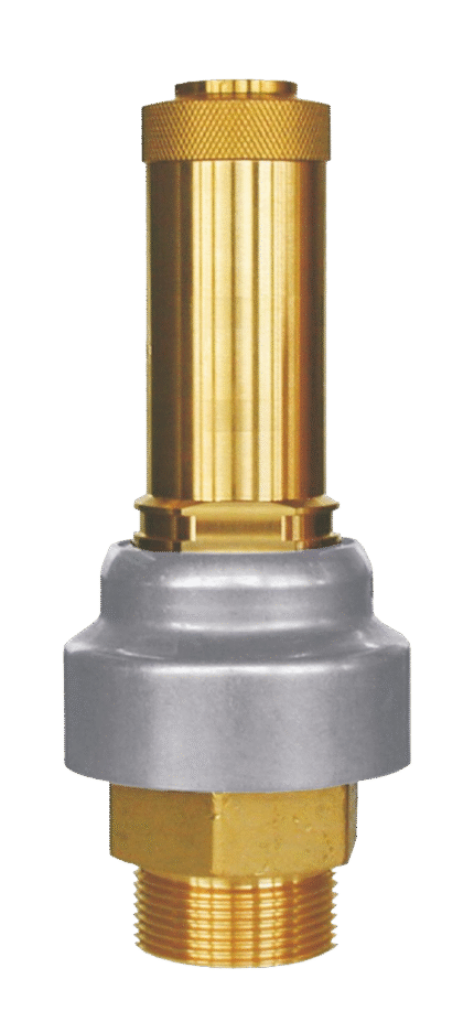
Related products
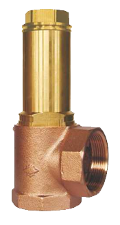
BRONZE PROPORTIONAL SAFETY VALVE THREADED HEROSE 06195
BRONZE PROPORTIONAL SAFETY VALVE THREADED HEROSE 06370
BRONZE PROPORTIONAL SAFETY VALVE THREADED HEROSE 06380
BRONZE PROPORTIONAL SAFETY VALVE THREADED HEROSE 06505

CAST IRON FULL-LIFT SAFETY VALVE DIN THREADED
SAFETY VALVE STEEL FULL-LIFT FLANGED DIN
STAINLESS STEEL FULL-LIFT SAFETY VALVE DIN THREADED