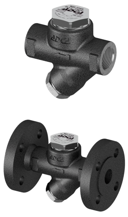
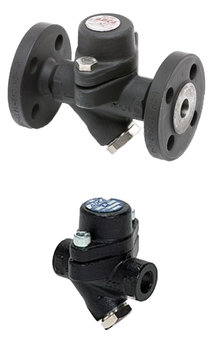
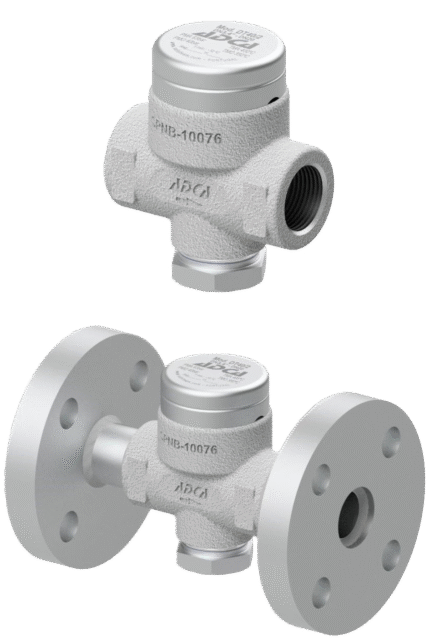
THERMODYNAMIC THREADED / FLANGED CONDENSATE TRAP ADCA DT 46
TECHNICAL DESCRIPTION
Thermodynamic steam traps model ADCA DT 46 are compact and easy to install and are excellent for installation in systems with high operating pressure, including “Stream tracing” applications. The insulating coating ensures consistent operation and makes them practically applicable for those applications where weather conditions, such as rain and wind, affect their normal functioning. Condensate traps of this type have only one moving element and are used in a wide range of operating pressures, without additional adjustment. The connection is female threaded or flanged.
MAIN FUNCTIONS
Discontinuous unloading. Standard insulation coating. Operation with superheated steam. Seat and valve can be replaced in the field without dismantling the steam trap. Not affected by hydraulic shocks and vibrations in the system. Built-in filter easy to service.
WORKING FLUIDS / MEDIUM
• Saturated and superheated steam.
EXECUTION
• threaded ISO 7 / 1 Rp (BS21)
• flanged EN 1092-1 PN40÷PN100 or ANSI.
• welded (on request)
OPTIONS:
• Purge valve.
Dimensions:1/2″ – 1″ / DN 15 – 25
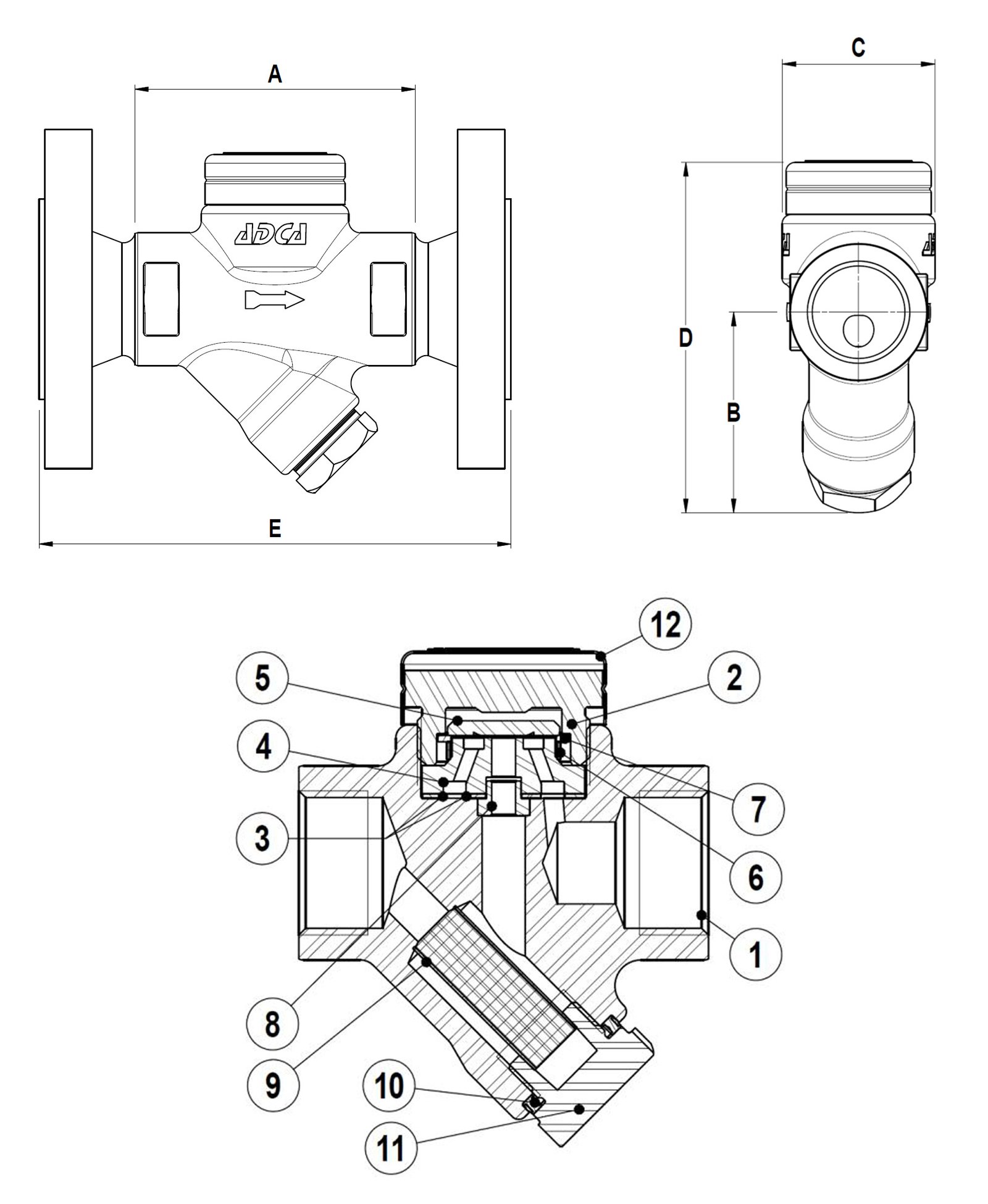
Materials
| No. | DETAILS | MATERIALS |
|---|---|---|
| 1 | Body | P250GH / 1.0460 |
| 2 | Lid | AISI 304 / 1.4301 AISI 303 / 1.4305 |
| 3 | Garnish | stainless steel / graphite |
| 4 | Saddle | improved stainless steel |
| 5 | Valve | improved stainless steel |
| 8 | Bushing | AISI 304 / 1.4301 |
| 9 | Filter screen | AISI 304 / 1.4301 |
| 10 | Garnish | stainless steel / graphite |
| 11 | Tapa | A105 / 1.0432 |
| 12 | Insulating coating | AISI 304 / 1.4301 |
Features
| SPECIFICATION | |
|---|---|
| Standard | DIN |
| Joining | thread BSP / flanged |
| Lid connection | threaded |
| Execution | straight |
| Management | automatically |
| Venting | automatically |
| Installation | horizontal |
Flow rate
| PASSABILITY (kg/h) | |||||||||||||||
|---|---|---|---|---|---|---|---|---|---|---|---|---|---|---|---|
| MODEL | DN | DIFFERENTIAL PRESSURE (bar) | |||||||||||||
| 1.5 | 3 | 5 | 7 | 9 | 12 | 15 | 18 | 21 | 24 | 30 | 35 | 42 | 46 | ||
| DT 46 (hot) | DN 15 - DN 25 | 70 | 100 | 130 | 175 | 190 | 200 | 225 | 240 | 250 | 270 | 290 | 300 | 310 | 320 |
| 1/2" - 1" | 70 | 100 | 130 | 175 | 190 | 200 | 225 | 240 | 250 | 270 | 290 | 300 | 310 | 320 | |
| DT 46 (cold) | DN 15 - DN 25" | 170 | 230 | 300 | 335 | 390 | 435 | 485 | 520 | 575 | 600 | 645 | 695 | 740 | 800 |
| 1/2" - 1" | 170 | 230 | 300 | 335 | 390 | 435 | 485 | 520 | 575 | 600 | 645 | 695 | 740 | 800 | |
Limits
| MAXIMUM OPERATING PARAMETERS | |||||
|---|---|---|---|---|---|
| Maximum working pressure / Bars | T max. [°C] | ||||
| FLANGE PN 40 / ANSI 300 |
FLANGE ANSI #150 |
FLANGED PN 63 |
FLANGED PN 100 |
FLANGE ANSI #600 |
|
| 40 bar | 19.3 bar | 63 bar | 100 bar | 90.5 bar | 50 °C |
| 37.1 bar | 17.7 bar | 58.5 bar | 92.8 bar | 80.2 bar | 100 °C |
| 33.3 bar | 14 bar | 52.5 bar | 83.3 bar | 72 bar | 200 °C |
| 27.6 bar | 10.2 bar | 43.5 bar | 69 bar | 59.7 bar | 300 °C |
| 23.8 bar | 6.5 bar | 37.5 bar | 59.5 bar | 51.4 bar | 400 °C |
| Threaded or welded | FLANGES EN PN 16 / PN 40 | FLANGED EN PN 63 | ANSI 150 FLANGES | ANSI 300 FLANGES | |||||||||
|---|---|---|---|---|---|---|---|---|---|---|---|---|---|
| DN | A | B | C | D | kg | E | kg | E | kg | E | kg | E | kg |
| 15 - 1/2" | 95 | 60 | 50 | 109 | 1.3 | 150 | 2.8 | 150 | 3.7 | 150 | 3.9 | 150 | 4.9 |
| 20 - 3/4" | 95 | 60 | 50 | 109 | 1.2 | 150 | 3.3 | 150 | 5.2 | 150 | 4.8 | 150 | 7 |
| 25 - 1" | 95 | 66 | 50 | 115 | 1.5 | 160 | 4.1 | 160 | 6.7 | 160 | 6.5 | 160 | 8.5 |
Related products
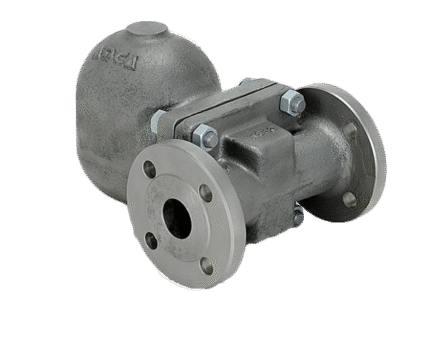
CONDENSATE SEPARATOR FLOAT THREADED / FLANGE ADCA FLT 14I DN 15 – 20
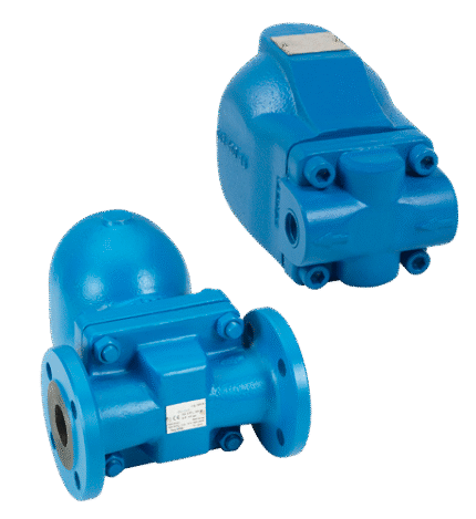
CONDENSATE SEPARATOR THERMODYNAMIC FLANGE TLV AF3N
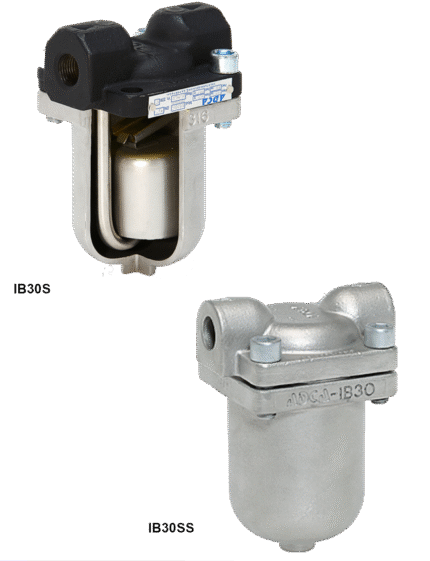
CONDENSATE TRAP WITH INVERTED PISTON ADCA IB30S / IB30SS
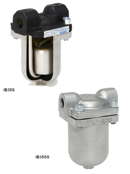
CONDENSATE TRAPPER WITH INVERTED PISTON ADCA IB35S / IB35SS
FLOAT FLANGE / THREADED CONDENSATE SEPARATOR ADCA FLT 14I – DN 40-50
FLOAT SEPARATOR THREADED / FLANGE ADCA FLT 17
THERMODYNAMIC THREADED / FLANGED CONDENSATE TRAP ADCA DT 40/2