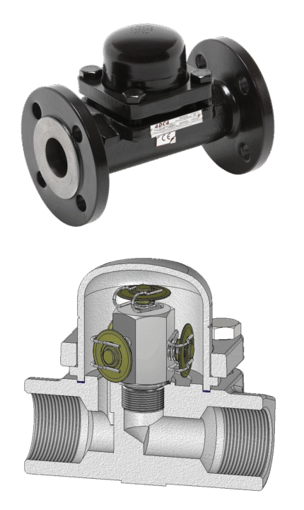
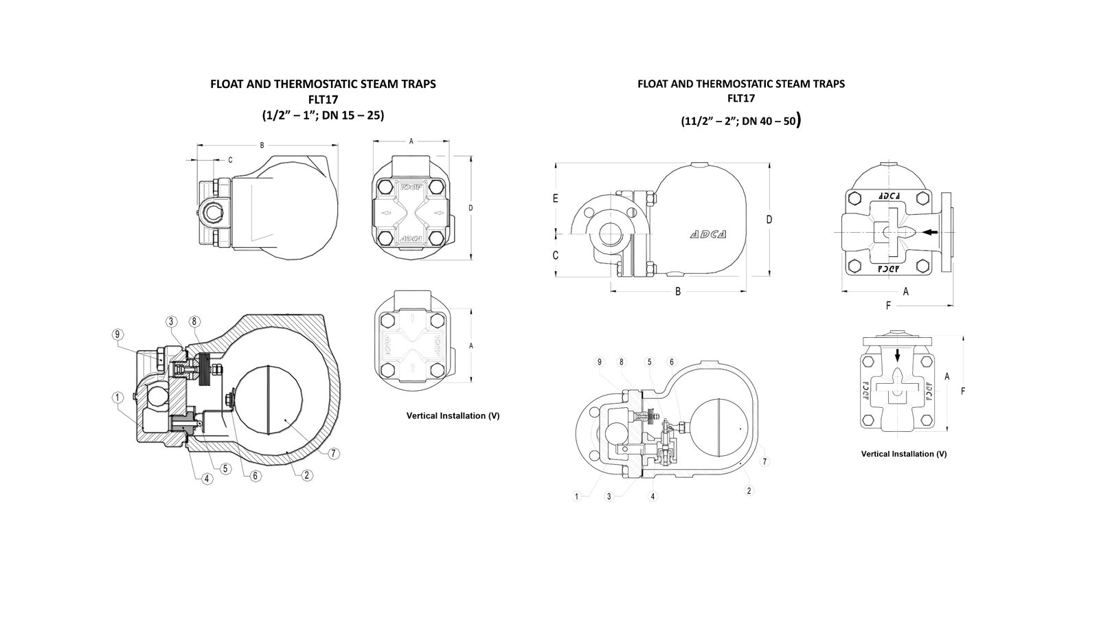
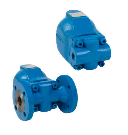
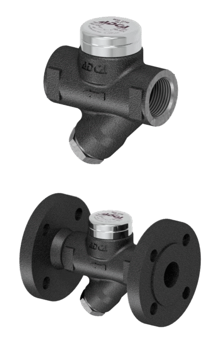
FLOAT SEPARATOR THREADED / FLANGE ADCA FLT 17
TECHNICAL DESCRIPTION
The float mechanism ensures direct drainage (removal) of the condensate from the steam system. In turn, the automatic air vent ensures the system is freed from uncondensed gases. Float condensate separators are designed primarily for horizontal installation. There are also versions for vertical installation, but the latter are made to order. Condensate separators of this type are designed to operate with a maximum differential pressure of 4.5 Bar. The capacity that is provided can be found in the additional information to the product description.
MAIN FUNCTIONS
To drain (remove) the condensate from the steam installation.
WORKING FLUID / MEDIUM
Steam.
EXECUTION
• SLR version (Steam lock release)
• Regulating needle valve
• Built-in internal filter element
• Installation – horizontal with fluid direction from left to right
• Installation – vertical with fluid direction from top to bottom
• Thermostatic air vent
Dimensions:1/2″ – 2″
Materials
| No. | POSITION | MATERIAL |
|---|---|---|
| 1 | Body | malleable cast iron GJS-400-15 / 0.7040 |
| 2 | Lid | malleable cast iron GJS-400-15 / 0.7040 |
| 3 | Gasket | stainless steel / graphite |
| 4.1 | Seat from DN15 to DN25 | stainless steel AISI 410 / 1.4006 |
| 4.2 | Seat from DN40 to DN50 | stainless steel CF8 / 1.4308 |
| 5.1 | Valve | stainless steel AISI 440C / 1.4125 |
| 5.2 | Valve | stainless steel AISI 420C / 1.4021 |
| 6 | Lever | stainless steel AISI 304 / 1.4301 |
| 7 | Float | stainless steel AISI 304 / 1.4301 |
| 8 | Thermostatic air vent | stainless steel (bimetallic) |
| 9 | Bolt | steel grade 8.8 |
Features
| SPECIFICATION | |
|---|---|
| Standard | DIN |
| Joining standard | BSPP thread / Flanged EN1092-2, ANSI 150 |
| Lid connection | bolted |
| Execution | straight |
| Management | automatically |
| Venting | automatically |
| Maximum differential pressure | 4.5; 10; 14 Bar |
| Installation | horizontal / vertical |
| PASSABILITY (kg/h) | |||||||||||||||||
|---|---|---|---|---|---|---|---|---|---|---|---|---|---|---|---|---|---|
| MODEL | SIZE | DIFFERENTIAL PRESSURE (bar) | |||||||||||||||
| DN | 0.1 | 0.3 | 0.5 | 0.7 | 1 | 1.5 | 2 | 3 | 4.5 | 6 | 7 | 8 | 9 | 10 | 12 | 14 | |
| FLT17-4.5 | 15 - 25 | 165 | 205 | 230 | 280 | 330 | 400 | 440 | 535 | 630 | - | - | - | - | - | - | - |
| FLT17-10 | 15 - 25 | 110 | 130 | 150 | 170 | 200 | 250 | 280 | 340 | 400 | 460 | 495 | 520 | 550 | 595 | - | - |
| FLT17-14 | 15 - 25 | 80 | 100 | 120 | 140 | 150 | 190 | 220 | 260 | 320 | 380 | 400 | 425 | 440 | 480 | 510 | 550 |
| MODEL | SIZE | DIFFERENTIAL PRESSURE (bar) | |||||||||||||||
| DN | 0.1 | 0.3 | 0.5 | 0.7 | 1 | 1.5 | 2 | 4.5 | 7 | 10 | 12 | 14 | |||||
| FLT17-4.5 | 40 - 50 | 1050 | 1750 | 2400 | 2700 | 3400 | 3900 | 4500 | 7300 | - | - | - | - | ||||
| FLT17-10 | 40 - 50 | 650 | 1100 | 1500 | 1700 | 2000 | 2600 | 3000 | 4000 | 5400 | 6200 | - | - | ||||
| FLT17-14 | 40 - 50 | 430 | 720 | 950 | 1100 | 1300 | 1600 | 1800 | 2600 | 3250 | 3900 | 4210 | 4950 | ||||
Related products
CONDENSATE SEPARATOR FLOAT THREADED / FLANGE ADCA FLT 32
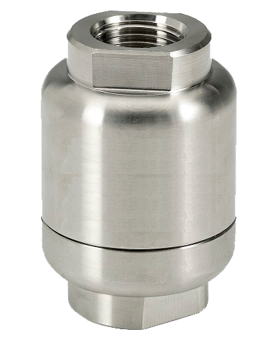
CONDENSATE TRAP WITH AIR BREATHER ADCA TSS 22 THREADED
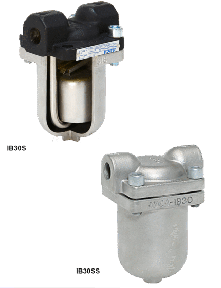
CONDENSATE TRAP WITH INVERTED PISTON ADCA IB30S / IB30SS
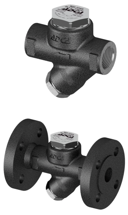
THERMODYNAMIC THREADED / FLANGED CONDENSATE TRAP ADCA DT 42/2
THERMODYNAMIC THREADED / FLANGED CONDENSATE TRAP ADCA DT 46
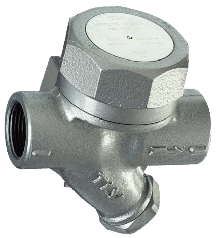
THERMODYNAMIC THREADED CONDENSATE TRAP TLV A3N
THERMOSTATIC CONDENSATE TRAP WITH AIR BREATHER THREADED / FLANGED ADCA TH35/2 – TH35/3