
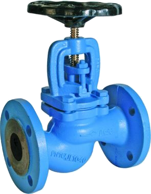
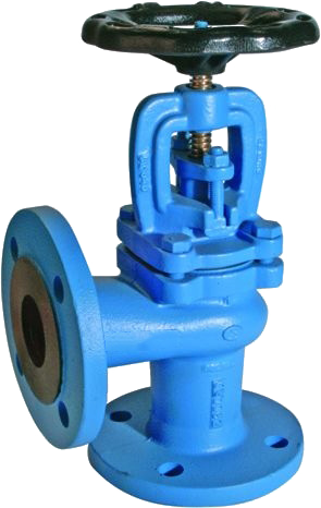
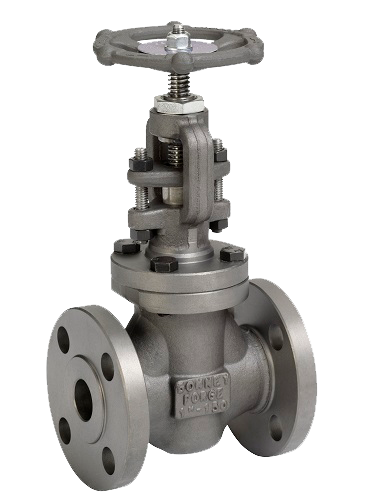
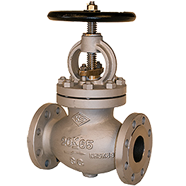
CAST IRON ANGLE VALVE DIN 3202 F32, PN 10
TECHNICAL DESCRIPTION
Angle valve, with flange connection. Possible variations of functions depending on the design:
• shut-off valve
• regulating valve
• check valve
Valve seal – metal to metal.
Spindle type – pull-out.
WORKING FLUID / MEDIUM
Water, steam, fuels, lubricating and combustible hydraulic oils, petroleum, seawater.
OPTIONS
Closing spring when functioning as a check valve.
Dimensions: DN 15 – 300
Additional information
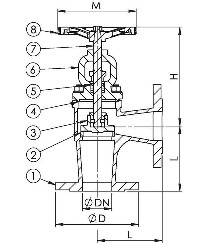
Materials
| No. | DETAILS | MATERIALS |
|---|---|---|
| 1 | Body | gray cast iron EN-JL1040 (GG25) |
| 2 | Saddle | stainless steel 1.4301 |
| 3 | Valve | gray cast iron EN-JL1040 (GG25)/1.4301 |
| 4 | Garnish | graphite |
| 5 | Oil seal | graphite packing |
| 6 | Lid | gray cast iron EN-JL1040 (GG25) |
| 7 | Spindle | stainless steel 1.4301 |
| 8 | Handwheel | gray cast iron EN-JL1040 (GG25) |
Features
| SPECIFICATION | |
|---|---|
| Standard | DIN 3202 F32 |
| Joining | EN 1092-2 |
| Construction length | EN 558, series 1 |
| Lid connection | bolted |
| Execution | angular |
| Joining | flanged |
| Management | manually with wheel |
| Drive | multi-turn |
| T max. °C | 180 °C |
Dimensions
| DN | PN | Flanges/PN | L | D | ØP* | nxd | H | M | Weight (kg) |
|---|---|---|---|---|---|---|---|---|---|
| 15 | 10 | 10 | 90 | 95 | 65 | 4x14 | 173 | 120 | 4 |
| 20 | 10 | 10 | 95 | 105 | 75 | 4x14 | 173 | 120 | 4.5 |
| 25 | 10 | 10 | 100 | 115 | 85 | 4x14 | 190 | 120 | 5.2 |
| 32 | 10 | 10 | 105 | 140 | 100 | 4x18 | 190 | 120 | 6.7 |
| 40 | 10 | 10 | 115 | 150 | 110 | 4x18 | 225 | 140 | 9.6 |
| 50 | 10 | 10 | 125 | 165 | 125 | 4x18 | 218 | 140 | 12 |
| 65 | 10 | 10 | 145 | 185 | 145 | 8x18 | 246 | 140 | 16 |
| 80 | 10 | 10 | 155 | 200 | 160 | 8x18 | 274 | 160 | 21 |
| 100 | 10 | 10 | 175 | 220 | 180 | 8x18 | 303 | 160 | 33 |
| 125 | 10 | 10 | 200 | 250 | 210 | 8x18 | 310 | 200 | 43 |
| 150 | 10 | 10 | 225 | 285 | 240 | 8x22 | 360 | 200 | 70 |
| 200 | 10 | 10 | 275 | 340 | 295 | 8x22 | 488 | 400 | 110 |
| 250 | 10 | 10 | 325 | 395 | 350 | 12x22 | 550 | 400 | 160 |
| 300 | 10 | 10 | 375 | 445 | 400 | 12x22 | 786 | 500 | 280 |
| Note: The dimensions in column ØP should be considered as the diameters of the bolt circle, as the latter are not indicated in the drawing. | |||||||||
Related products
Select options
This product has multiple variants. The options may be chosen on the product page
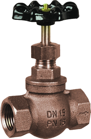
BRASS ANGLE VALVE WITH THREADED COVER DIN 3202 F32, PN 16
Select options
This product has multiple variants. The options may be chosen on the product page
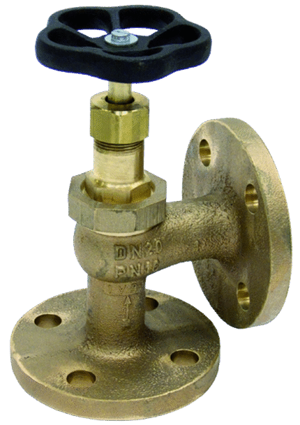
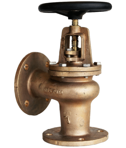
BRONZE ANGLE VALVE WITH BOLT COVER DIN 3202 F32, PN 16
Select options
This product has multiple variants. The options may be chosen on the product page
BRONZE THREADED STRAIGHT VALVE DIN 3202 F1, PN 16
Select options
This product has multiple variants. The options may be chosen on the product page
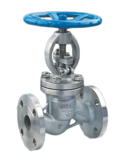
STAINLESS STEEL VALVE STRAIGHT DIN 3202 F1, PN 40
Select options
This product has multiple variants. The options may be chosen on the product page
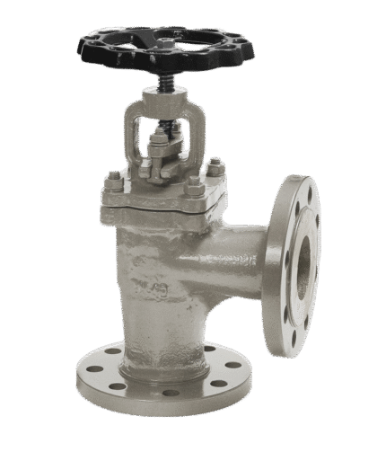
STEEL ANGLE VALVE DIN 3202 F32, PN 10

Select options
This product has multiple variants. The options may be chosen on the product page
STEEL ANGLE VALVE DIN 3202 F32, PN 40
Select options
This product has multiple variants. The options may be chosen on the product page
STEEL FORGED VALVE ON FLANGES ANSI #600
Select options
This product has multiple variants. The options may be chosen on the product page